VENTING
D. HEATER REMOVAL FROM A COMMON VENT SYSTEM
At the time of removal of an existing heater, the following steps shall be followed with each appli- ance remaining connected to the common venting system placed in operation, while the other appliances remaining connected to common venting system are not operating.
1.Seal any unused openings in the common venting system.
2.Visually inspect the venting system for proper size and horizontal pitch to determine if there is blockage, leakage, corrosion or other deficiencies that could cause an unsafe condition.
3.If practical, close all building doors, windows and all doors between the space in which the appliance remains connected to the common venting system located and other spaces in the building. Turn on clothes dryers and any appliances not connected to the common vent- ing system. Turn on any exhaust fans, such as range hoods and bathroom exhausts, at max- imum speed. Do not operate a summer exhaust fan. Close all fireplace dampers.
4.Place in operation the appliance being inspected. Follow the lighting instructions. Adjust the thermostat so the appliance will operate continuously.
5.Test for spillage at the draft hood relief opening after 5 minutes of main burner operation. Use the flame of a match or candle or smoke from a cigarette.
6.After it has been determined that each appliance remaining connected to common venting system properly vents when tested as outlined, return doors, windows, exhaust fans, fire- place dampers and any other gas burning appliance to their previous condition of use.
7.Any improper operation of the common venting system should be corrected so the installa- tion conforms with the National Fuel Gas Code, ANSI Z223.1. When resizing any portion of the common venting system, the common venting system should be resized to approach the minimum size as determined using the appropriate tables in Appendix G in the National Fuel Gas Code , ANSI Z 223.1
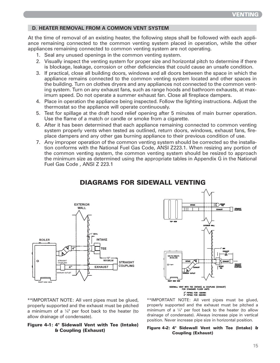
DIAGRAMS FOR SIDEWALL VENTING
**IMPORTANT NOTE: All vent pipes must be glued, properly supported and the exhaust must be pitched a minimum of a ¼" per foot back to the heater (to allow drainage of condensate).
Figure 4-1: 4" Sidewall Vent with Tee (Intake) & Coupling (Exhaust)
**IMPORTANT NOTE: All vent pipes must be glued, properly supported and the exhaust must be pitched a minimum of a ¼" per foot back to the heater (to allow drainage of condensate). Always increase pipe in vertical position. Never increase pipe size in horizontal position.
Figure 4-2: 4" Sidewall Vent with Tee (Intake) & Coupling (Exhaust)
15