PIPING
pound. Threaded connections are 2” NPT Brass nipples located on the left hand side of unit.
2.Connect the system supply marked “Heater Out”, make sure to install with pipe sealant com- pound. Threaded connections are 2” NPT Brass nipples located on the left hand side of the unit.
3.Install Purge and Balance Valve or shut off valve and drain on system return to purge air out of each zone.
4.Install a Back Flow preventor on the Cold Feed
5.Install a Pressure Reducing Valve on the Cold Feed
6.Install a circulator on system supply. Make sure the circulator is properly sized for the system and friction loss.
7.Install an Expansion Tank on the system supply. Consult the tank manufacturer’s instruction for specific information relating to tank installation. Size the expansion tank for the required system volume and capacity.
8.Install an Air Elimination Device on the system supply.
9.Install a drain valve at the lowest point of the system. Note: The Munchkin can not be drained completely of water without purging the unit with an air pressure 15 PSI.
10.The Safety Relief Valve is installed at the factory located on the right hand side of Munchkin. Pipe the discharge of safety relief valve to prevent injury in the event of pressure relief. Pipe the discharge to a drain. Provide piping that is the same size as the safety relief valve outlet. Never block the outlet of safety relief valve.
See the piping illustrations included in this section, Figs.
*Please note that these illustrations are meant to show system piping concept only, the installer is responsible for all equipment and detailing required by local codes.
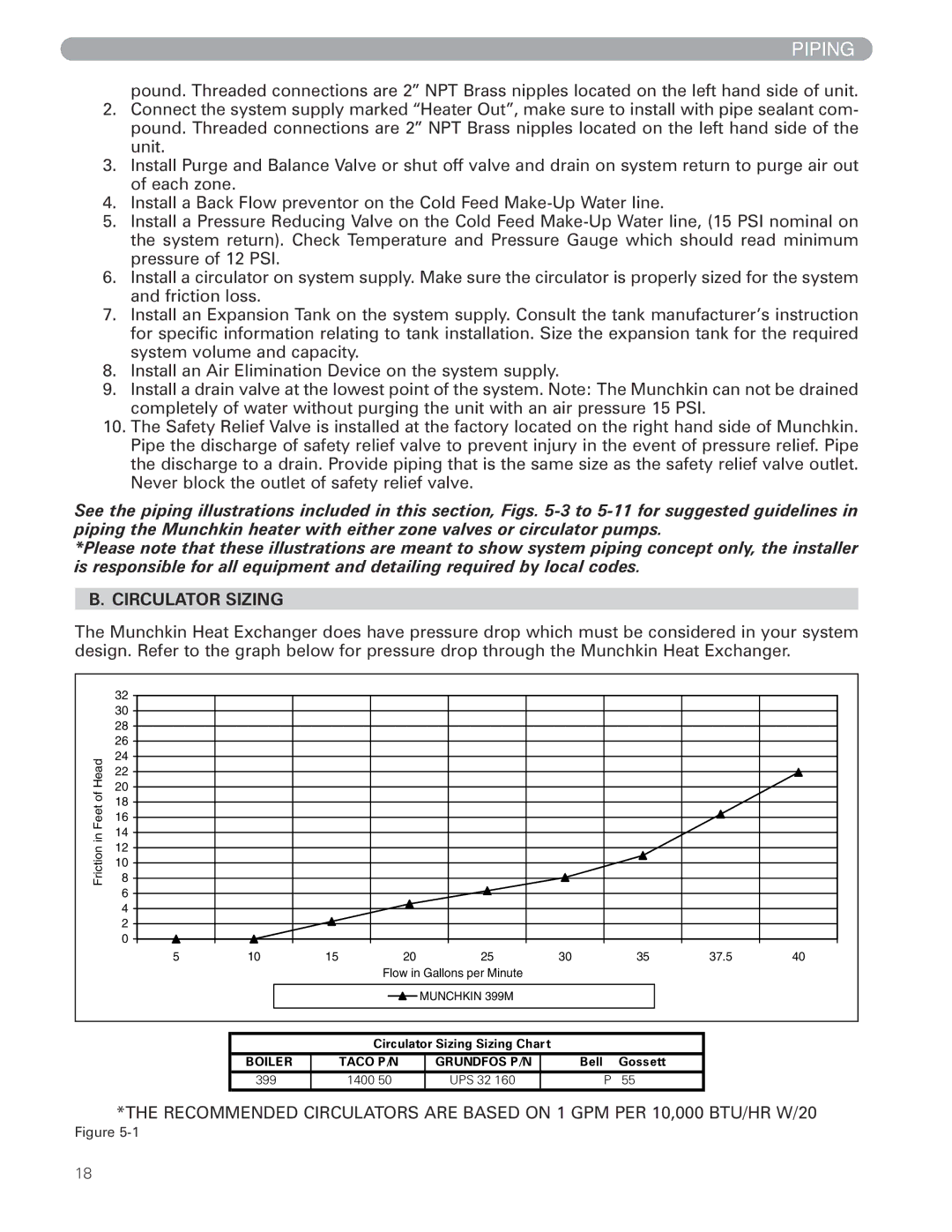
B. CIRCULATOR SIZING
The Munchkin Heat Exchanger does have pressure drop which must be considered in your system design. Refer to the graph below for pressure drop through the Munchkin Heat Exchanger.
| 32 |
|
|
|
|
|
|
|
|
| 30 |
|
|
|
|
|
|
|
|
| 28 |
|
|
|
|
|
|
|
|
| 26 |
|
|
|
|
|
|
|
|
Head | 24 |
|
|
|
|
|
|
|
|
22 |
|
|
|
|
|
|
|
| |
20 |
|
|
|
|
|
|
|
| |
of |
|
|
|
|
|
|
|
| |
18 |
|
|
|
|
|
|
|
| |
Feet |
|
|
|
|
|
|
|
| |
16 |
|
|
|
|
|
|
|
| |
14 |
|
|
|
|
|
|
|
| |
in |
|
|
|
|
|
|
|
| |
12 |
|
|
|
|
|
|
|
| |
Friction |
|
|
|
|
|
|
|
| |
10 |
|
|
|
|
|
|
|
| |
8 |
|
|
|
|
|
|
|
| |
| 6 |
|
|
|
|
|
|
|
|
| 4 |
|
|
|
|
|
|
|
|
| 2 |
|
|
|
|
|
|
|
|
| 0 |
|
|
|
|
|
|
|
|
| 5 | 10 | 15 | 20 | 25 | 30 | 35 | 37.5 | 40 |
Flow in Gallons per Minute
![]() MUNCHKIN 399M
MUNCHKIN 399M
Circulator Sizing Sizing Chart
BOILER | TACO P/N | GRUNDFOS P/N | Bell & Gossett |
399M | UPS |
*THE RECOMMENDED CIRCULATORS ARE BASED ON 1 GPM PER 10,000 BTU/HR W/20
Figure
18