local audible (K-4) terminal 20 and 21, remote audible (K-5) terminal 22 and 23 and remote visual (K- 6) terminal 24 and 25 close to operate the alarm devices wired to them.
7-3.3An alarm silence pushbutton is wired between terminal 35 and ground. This switch is provided on the A901 and can be externally connected on the A902 series. When this switch is closed, the audible alarm relays K-4 and K-5 will drop out if they are closed. This turns off the audible alarms but does not affect the individual alarm lights on the panel. The lights will remain on until the input switches open. If no alarm silence switch is provided, the alarm relays will reset when the alarm and / or shutdown lights reset.
Section 8: Service Parts
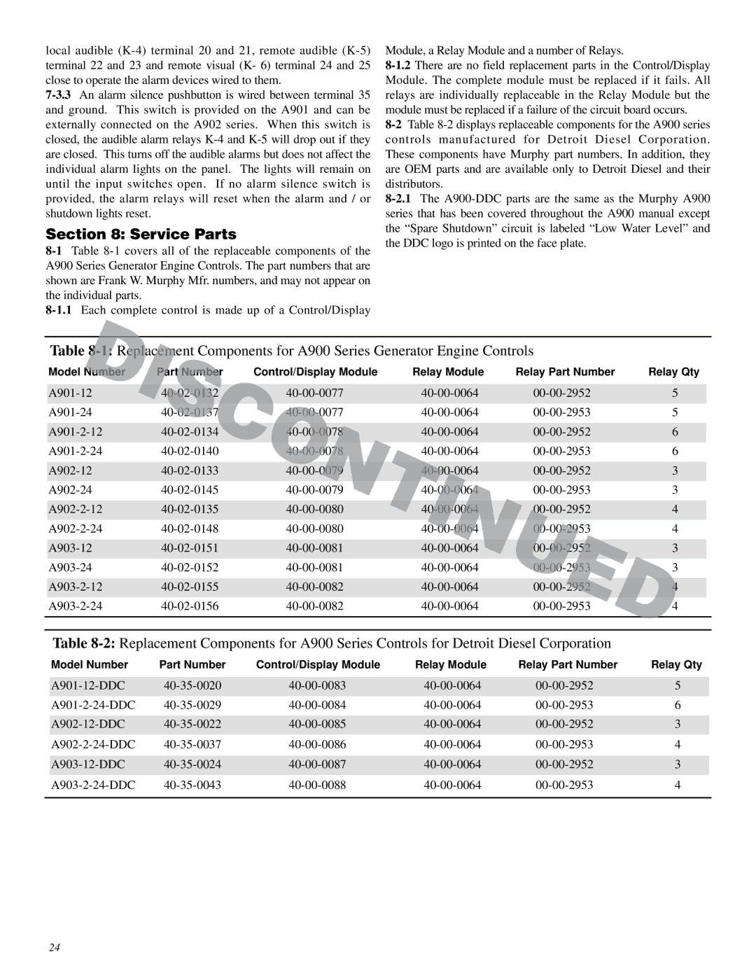
8-1Table 8-1 covers all of the replaceable components of the A900 Series Generator Engine Controls. The part numbers that are shown are Frank W. Murphy Mfr. numbers, and may not appear on the individual parts.
8-1.1Each complete control is made up of a Control/Display
Module, a Relay Module and a number of Relays.
8-1.2There are no field replacement parts in the Control/Display Module. The complete module must be replaced if it fails. All relays are individually replaceable in the Relay Module but the module must be replaced if a failure of the circuit board occurs.
8-2Table 8-2 displays replaceable components for the A900 series controls manufactured for Detroit Diesel Corporation. These components have Murphy part numbers. In addition, they are OEM parts and are available only to Detroit Diesel and their distributors.
8-2.1The A900-DDC parts are the same as the Murphy A900 series that has been covered throughout the A900 manual except the “Spare Shutdown” circuit is labeled “Low Water Level” and the DDC logo is printed on the face plate.
Table 8-1:Replacement Components for A900 Series Generator Engine Controls
| Model Number | Part Number | Control/Display Module | Relay Module | Relay Part Number | Relay Qty | |
| | | | | | | |
| A901-12 | 40-02-0132 | 40-00-0077 | 40-00-0064 | 00-00-2952 | 5 | |
| | | | | | | |
| A901-24 | 40-02-0137 | 40-00-0077 | 40-00-0064 | 00-00-2953 | 5 | |
| | | | | | | |
| A901-2-12 | 40-02-0134 | 40-00-0078 | 40-00-0064 | 00-00-2952 | 6 | |
| | | | | | | |
| A901-2-24 | 40-02-0140 | 40-00-0078 | 40-00-0064 | 00-00-2953 | 6 | |
| | | | | | | |
| A902-12 | 40-02-0133 | 40-00-0079 | 40-00-0064 | 00-00-2952 | 3 | |
| | | | | | | |
| A902-24 | 40-02-0145 | 40-00-0079 | 40-00-0064 | 00-00-2953 | 3 | |
| | | | | | | |
| A902-2-12 | 40-02-0135 | 40-00-0080 | 40-00-0064 | 00-00-2952 | 4 | |
| | | | | | | |
| A902-2-24 | 40-02-0148 | 40-00-0080 | 40-00-0064 | 00-00-2953 | 4 | |
| | | | | | | |
| A903-12 | 40-02-0151 | 40-00-0081 | 40-00-0064 | 00-00-2952 | 3 | |
| | | | | | | |
| A903-24 | 40-02-0152 | 40-00-0081 | 40-00-0064 | 00-00-2953 | 3 | |
| | | | | | | |
| A903-2-12 | 40-02-0155 | 40-00-0082 | 40-00-0064 | 00-00-2952 | 4 | |
| | | | | | | |
| A903-2-24 | 40-02-0156 | 40-00-0082 | 40-00-0064 | 00-00-2953 | 4 | |
| | | | | | | |
| | | | | | | |
Table 8-2:Replacement Components for A900 Series Controls for Detroit Diesel Corporation
| Model Number | Part Number | Control/Display Module | Relay Module | Relay Part Number | Relay Qty | |
| | | | | | | |
| A901-12-DDC | 40-35-0020 | 40-00-0083 | 40-00-0064 | 00-00-2952 | 5 | |
| | | | | | | |
| A901-2-24-DDC | 40-35-0029 | 40-00-0084 | 40-00-0064 | 00-00-2953 | 6 | |
| | | | | | | |
| A902-12-DDC | 40-35-0022 | 40-00-0085 | 40-00-0064 | 00-00-2952 | 3 | |
| | | | | | | |
| A902-2-24-DDC | 40-35-0037 | 40-00-0086 | 40-00-0064 | 00-00-2953 | 4 | |
| | | | | | | |
| A903-12-DDC | 40-35-0024 | 40-00-0087 | 40-00-0064 | 00-00-2952 | 3 | |
| | | | | | | |
| A903-2-24-DDC | 40-35-0043 | 40-00-0088 | 40-00-0064 | 00-00-2953 | 4 | |
| | | | | | | |
