Murphy Series A900 manual 3-5 A902-2, DC12V DC12V DC12V

Models: Series A900

1 28
Download 28 pages 37.11 Kb
Page 11
Image 11
DC12V DC12V

setting until the overspeed trips. When switch is released, the set point will be 10% above normal running speed. This is the method used to make the factory setting. With engine speed at 1800 RPM or 3540 Hz.

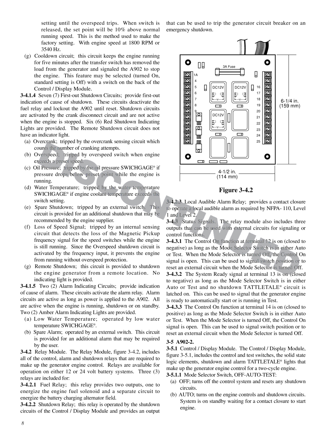
that can be used to trip the generator circuit breaker on an emergency shutdown.

(g)Cooldown circuit; this circuit keeps the engine running for five minutes after the transfer switch has removed the load from the generator and signaled the A902 to stop the engine. This feature may be selected (turned On, standard setting is Off) with a switch on the back of the Control / Display Module.

3-4.1.4Seven (7) First-out Shutdown Circuits; provide first-out indication of cause of shutdown. These circuits deactivate the fuel relay and lockout the A902 until reset. Shutdown circuits are activated by the crank disconnect circuit and are not active when the engine is stopped. Six (6) Red Shutdown Indicating Lights are provided. The Remote Shutdown circuit does not have an indicator light.

(a)

Overcrank; tripped by the overcrank sensing circuit which


counts the number of cranking attempts.

(b) Overspeed; tripped by overspeed switch when engine


exceeds a preset speed.

(c)

Oil Pressure; tripped by the oil pressure SWICHGAGE® if

1A

4

5

6

7

8

9

3A Fuse

DC12V DC12V

DC12V

16

17

18

19

20

21

22

23

24

25

6-1/4 in.

(159 mm)


pressure drops below preset point while the engine is


running.

(d)

Water Temperature; tripped by the water temperature


SWICHGAGE® if engine coolant temperature exceeds the


switch setting.

(e)

Spare Shutdown; tripped by an external switch. This


circuit is provided for an additional shutdown that may be


recommended by the engine supplier.

(f)

Loss of Speed Signal; tripped by an internal sensing


circuit that detects the loss of the Magnetic Pickup


frequency signal for the speed switches while the engine


is still running. Since the Overspeed shutdown circuit is


activated by the frequency input, it prevents the engine


from running without overspeed protection.

(g)

Remote Shutdown; this circuit is provided to shutdown


the engine generator from a remote location. No


indicating light is provided.

3-4.1.5Two (2) Alarm Indicating Circuits; provide indication of cause of alarm. These circuits activate the alarm relay. Alarm circuits are active as long as power is applied to the A902. All are active when the engine is running, shutdown or on standby. Two (2) Amber Alarm Indicating Lights are provided.

(a)Low Water Temperature; operated by low water temperature SWICHGAGE® .

(b)Spare Alarm; operated by an external switch. This circuit is provided for an additional alarm that may be required by the user.

3-4.2Relay Module. The Relay Module, figure 3-4.2, includes all of the control, alarm and shutdown relays that are required to make up the generator engine control. Relays are available for operation on either 12 or 24 volt battery systems. Three (3) relays are included for:

3-4.2.1Fuel Relay; this relay provides two outputs, one to energize the engine fuel solenoid and a separate circuit to energize the battery charging alternator field.

3-4.2.2Shutdown Relay; this relay is operated by the shutdown circuits of the Control / Display Module and provides an output

4-1/2 in.

(114 mm)

Figure 3-4.2

3-4.2.3Local Audible Alarm Relay; provides a contact closure to operate a local audible alarm as required by NFPA- 110, Level 1 and Level 2.

3-4.3Status Signals. The relay module also includes three outputs that can be used with external circuits for signaling or control functions.

3-4.3.1The Control On function at terminal 12 is on (closed to negative) as long as the Mode Selector Switch is in either Auto or Test. When the Mode Selector is turned Off, the Control On signal is open. This can be used to signal switch position or to reset an external circuit when the Mode Selector is turned Off.

3-4.3.2The System Ready signal at terminal 13 is on (closed to negative) as long as the Mode Selector Switch is in either Auto or Test and no shutdown TATTLETALE® circuit is latched on. This can be used to signal that the generator engine is ready to automatically start or is running in Test.

3-4.3.3The Control On function at terminal 14 is on (closed to positive) as long as the Mode Selector Switch is in either Auto or Test. When the Mode Selector is turned Off, the Control On signal is open. This can be used to signal switch position or to reset an external circuit when the Mode Selector is turned Off.

3-5 A902-2.

3-5.1Control / Display Module. The Control / Display Module, figure 3-5.1, includes the control and test switches, the solid state logic elements, shutdown and alarm TATTLETALE® lights that make up the generator engine control for a two-cycle engine.

3-5.1.1Mode Selector Switch, OFF-AUTO-TEST:

(a)OFF; turns off the control system and resets any shutdown circuits.

(b)AUTO; turns on the engine controls and shutdown circuits. System is on standby waiting for a contact closure to start engine.

8

Page 11
Image 11
Murphy Series A900 manual 3-5 A902-2, DC12V DC12V DC12V