energize the battery charging alternator field.
3-2.2.2Shutdown Relay; this relay is operated by the shutdown circuits of the Control / Display Module and provides an output that can be used to trip the generator circuit breaker on an emergency shutdown.
3-2.2.3Local Audible Alarm Relay; provides a contact closure to operate a local audible alarm as required by NFPA-110, Level 1 and Level 2.
3-2.2.4Remote Audible Alarm Relay; provides a contact closure to operate a remote audible alarm as required by NFPA- 110, Level 1.
3-2.2.5Remote Visual Alarm Relay; provides a contact closure to operate a remote visual alarm as required by NFPA- 110, Level 1.
3-2.3Status Signals. The relay module also includes three outputs that can be used with external circuits for signaling or control functions.
3-2.3.1The Control On function at terminal 12 is on (closed to negative) as long as the Mode Selector Switch is in either Auto or Test. When the Mode Selector is turned Off, the Control On signal is open. This can be used to signal switch position or to reset an external circuit when the Mode Selector is turned Off.
3-2.3.2The System Ready signal at terminal 13 is on (closed to negative) as long as the Mode Selector Switch is in either Auto or Test and no shutdown Tattletale circuit is latched on. This can be used to signal that the generator engine is ready to automatically start or is running in Test.
3-2.3.3The Control On function at terminal 14 is on (closed to positive) as long as the Mode Selector Switch is in either Auto or Test. When the Mode Selector is turned Off, the Control On signal is open. This can be used to signal switch position or to reset an external circuit when the Mode Selector is turned Off.
3-3 A901-2.
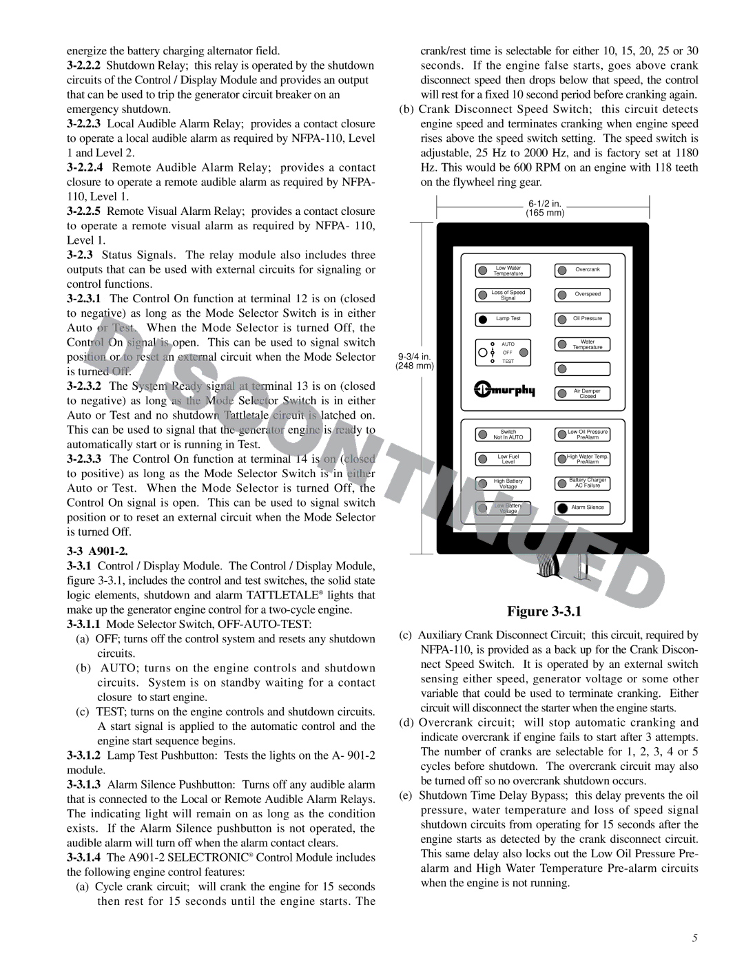
3-3.1Control / Display Module. The Control / Display Module, figure 3-3.1, includes the control and test switches, the solid state logic elements, shutdown and alarm TATTLETALE® lights that make up the generator engine control for a two-cycle engine.
3-3.1.1Mode Selector Switch, OFF-AUTO-TEST:
(a)OFF; turns off the control system and resets any shutdown circuits.
(b)AUTO; turns on the engine controls and shutdown circuits. System is on standby waiting for a contact closure to start engine.
(c)TEST; turns on the engine controls and shutdown circuits. A start signal is applied to the automatic control and the engine start sequence begins.
3-3.1.2Lamp Test Pushbutton: Tests the lights on the A- 901-2 module.
3-3.1.3Alarm Silence Pushbutton: Turns off any audible alarm that is connected to the Local or Remote Audible Alarm Relays. The indicating light will remain on as long as the condition exists. If the Alarm Silence pushbutton is not operated, the audible alarm will turn off when the alarm contact clears.
3-3.1.4The A901-2 SELECTRONIC® Control Module includes the following engine control features:
(a)Cycle crank circuit; will crank the engine for 15 seconds then rest for 15 seconds until the engine starts. The
crank/rest time is selectable for either 10, 15, 20, 25 or 30 seconds. If the engine false starts, goes above crank disconnect speed then drops below that speed, the control will rest for a fixed 10 second period before cranking again.
(b)Crank Disconnect Speed Switch; this circuit detects engine speed and terminates cranking when engine speed rises above the speed switch setting. The speed switch is adjustable, 25 Hz to 2000 Hz, and is factory set at 1180 Hz. This would be 600 RPM on an engine with 118 teeth on the flywheel ring gear.
6-1/2 in.
(165 mm)
| Low Water | Overcrank |
| Temperature | |
| Loss of Speed | Overspeed |
| Signal | |
| Lamp Test | Oil Pressure |
| AUTO | Water |
| Temperature |
| |
9-3/4 in. | OFF | |
TEST | |
(248 mm) | |
| |
| | Air Damper |
| | Closed |
| Switch | Low Oil Pressure |
| Not In AUTO | PreAlarm |
| Low Fuel | High Water Temp. |
| Level | PreAlarm |
| High Battery | Battery Charger |
| Voltage | AC Failure |
| Low Battery | Alarm Silence |
| Voltage |
| |
Figure 3-3.1
(c)Auxiliary Crank Disconnect Circuit; this circuit, required by NFPA-110, is provided as a back up for the Crank Discon- nect Speed Switch. It is operated by an external switch sensing either speed, generator voltage or some other variable that could be used to terminate cranking. Either circuit will disconnect the starter when the engine starts.
(d)Overcrank circuit; will stop automatic cranking and indicate overcrank if engine fails to start after 3 attempts. The number of cranks are selectable for 1, 2, 3, 4 or 5 cycles before shutdown. The overcrank circuit may also be turned off so no overcrank shutdown occurs.
(e)Shutdown Time Delay Bypass; this delay prevents the oil pressure, water temperature and loss of speed signal shutdown circuits from operating for 15 seconds after the engine starts as detected by the crank disconnect circuit. This same delay also locks out the Low Oil Pressure Pre- alarm and High Water Temperature Pre-alarm circuits when the engine is not running.