(f)Overspeed Speed Switch;
1.Provides a signal to the overspeed shutdown circuit if the engine exceeds the preset speed. The factory setting is approximately 3894 Hz, or 1980 RPM on an engine with 118 teeth on the flywheel ring gear. The adjustment range is 300 Hz to 10,000 Hz.
2.A push to test switch is provided to allow testing of the overspeed circuit without overspeeding the engine. When switch is depressed, the set point of the speed switch is lowered approximately 10%.
3.The push to test switch can also be used to set the overspeed switch at approximately 110% of running speed. Hold the switch depressed while adjusting the setting until the overspeed trips. When switch is released, the set point will be 10% above normal running speed. This is the method used to make the factory setting. With engine speed at 1800 RPM or 3540 Hz.
(g)Cooldown circuit; this circuit keeps the engine running for five minutes after the transfer switch has removed the load from the generator and signaled the
(a)Overcrank; tripped by the overcrank sensing circuit which counts the number of cranking attempts.
(b)Overspeed; tripped by overspeed switch when engine exceeds a preset speed.
(c)Oil Pressure; tripped by the oil pressure SWICHGAGE® if pressure drops below preset point while the engine is running.
(d)Water Temperature; tripped by the water temperature SWICHGAGE® if engine coolant temperature exceeds the switch setting.
(e)Spare Shutdown; tripped by an external switch. This circuit is provided for an additional shutdown that may be recommended by the engine supplier.
(f)Loss of Speed Signal; tripped by an internal sensing circuit that detects the loss of the Magnetic Pickup frequency signal for the speed switches while the engine is still running. Since the Overspeed shutdown circuit is activated by the frequency input, it prevents the engine from running without overspeed protection.
(g)Remote Shutdown; this circuit is provided to shutdown the engine generator from a remote location. No indicating light is provided.
(a)Low Water Temperature; operated by low water temp- erature SWICHGAGE® .
(b)Air Damper Closed; operated by an external switch or by the Overspeed Relay circuit. This circuit is provided with a selector switch to allow the user to determine the source of the signal.
(c)Switch Not In Automatic; operated by the
(d)Low Fuel Level; operated by level switch on fuel tank.
(e)High Battery Voltage; operated by relay contact in battery charger.
(f)Low Battery Voltage; operated by low voltage sensing device in battery charger.
(g)Low Oil Pressure
(h)High Water Temperature
(i)Battery Charger AC Failure; operated by relay contact in Battery Charger.
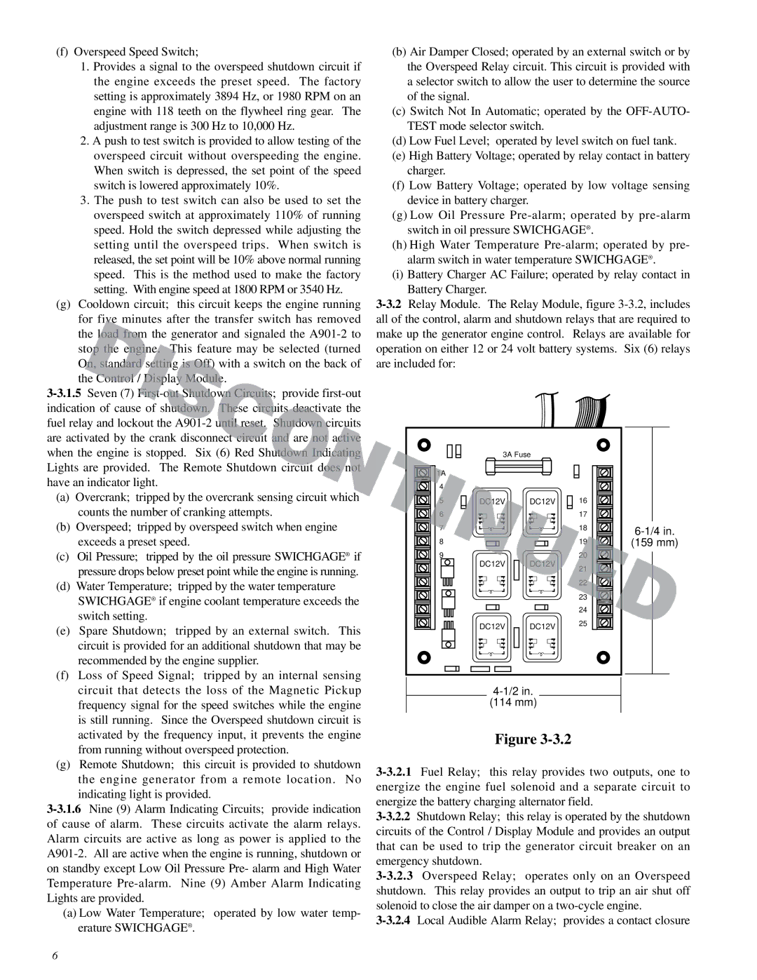
| 3A Fuse |
|
| |
1A |
|
|
|
|
4 |
|
|
|
|
5 | DC12V | DC12V | 16 |
|
6 |
|
| 17 |
|
7 |
|
| 18 | |
|
|
|
| |
8 |
|
| 19 | (159 mm) |
9 |
|
| 20 |
|
| DC12V | DC12V | 21 |
|
|
|
|
| |
|
|
| 22 |
|
|
|
| 23 |
|
|
|
| 24 |
|
| DC12V | DC12V | 25 |
|
|
|
| ||
|
|
| ||
| (114 mm) |
|
| |
Figure
6