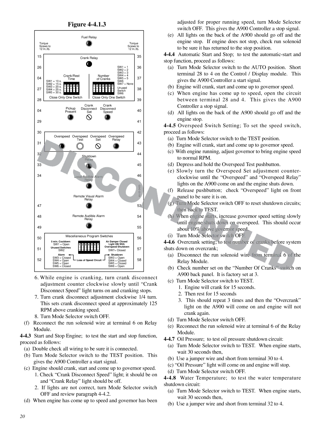
| Figure |
|
|
| ||||
|
|
| Fuel Relay |
|
|
|
| |
Torque |
|
|
|
|
|
| Torque | |
Scews to |
|
|
|
|
| Scews to | ||
12 In./lb. |
|
|
|
|
|
| 12 In./lb. | |
15 |
|
| Crank Relay |
|
|
| 35 | |
|
|
|
|
|
|
| ||
26 |
|
|
|
|
|
| SW1 = 1 | 36 |
|
|
|
|
|
|
| SW2 = 2 |
|
|
|
|
|
|
|
| SW3 = 3 |
|
04 | Crank/Rest | Number | SW4 = 4 | 37 | ||||
Time |
| of Cranks | SW5 = 5 | |||||
| SW1 = 10 s. |
|
|
|
|
| SW6 |
|
| SW2 = 15 s. |
|
|
|
|
| SW7 = None | |
| SW3 = 20 s. 1 2 3 | 4 | 5 | 1 2 | 3 4 5 6 | 7 |
| |
27 | SW4 = 25 s. |
|
|
|
|
| Unused | 38 |
|
|
|
|
| Switch | |||
| SW5 = 30 s. |
|
|
|
|
|
| |
|
|
|
|
|
| SW6 |
| |
|
|
|
|
|
|
|
| |
28 | Close Only One Switch | Close Only One Switch | 39 | |||||
|
|
|
|
|
|
| ||
| Pickup |
| Crank | Crank |
| |||
04 | Disconnect | Disconnect | 40 | |||||
Present |
| Set | Speed | |||||
|
|
| ||||||
29 |
|
|
|
|
|
|
| 41 |
30 |
|
|
|
|
|
|
| 42 |
| Overspeed | Overspeed Overspeed | Overspeed |
| ||||
31 |
|
| Test | Set |
| Relay | 43 | |
|
|
|
|
|
|
| ||
32 |
|
|
| hutdown |
|
|
| 44 |
|
|
|
|
|
|
|
| |
|
|
|
| Relay |
|
|
|
|
33 |
|
|
|
|
|
|
| 45 |
34 |
| Local Audible Alarm |
|
| 46 | |||
|
|
|
| Relay |
|
|
|
|
|
| Remote Visual Alarm |
|
| ||||
|
|
|
| Relay |
|
|
|
|
47 |
|
|
|
|
|
|
| 53 |
48 |
| Remote Audible Alarm |
|
| 54 | |||
|
|
|
| Relay |
|
|
|
|
49 |
|
|
|
|
|
|
| 55 |
50 | Miscellaneous Program Switches | 56 | ||||||
5 min. Cooldown |
|
|
| Air Damper Closed | ||||
|
|
|
|
| ||||
| SW1 = Open |
| 1 2 | 3 4 5 6 7 |
| Light ON With |
| |
| Unused Switches |
|
|
| Overspeed Shutdown | |||
51 |
|
|
|
| SW7= Closed | 57 | ||
SW2 |
|
|
|
| ||||
|
|
|
|
|
| |||
| Alarm |
|
|
|
|
| Shutdown |
|
52 | SW3 = Closed |
| Loss of Speed Circuit | SW3 = Open | 58 | |||
SW4 = Open |
| SW4 = Closed | ||||||
| SW5 = Open |
|
|
|
| SW5 = Closed |
| |
| SW6 = Closed |
|
|
|
| SW6 = Open |
| |
6.While engine is cranking, turn crank disconnect adjustment counter clockwise slowly until “Crank Disconnect Speed” light turns on and cranking stops.
7.Turn crank disconnect adjustment clockwise 1/4 turn. This sets crank disconnect speed at approximately 125 RPM above cranking speed.
8.Turn Mode Selector switch OFF.
(f)Reconnect the run solenoid wire at terminal 6 on Relay Module.
(a)Double check all wiring to be sure it is connected.
(b)Turn Mode Selector switch to the TEST position. This gives the A900 Controller a start signal.
(c)Engine should crank, start and come up to governor speed.
1.Check “Crank Disconnect Speed” light; it should be on and “Crank Relay” light should be off.
2.If lights are not correct, turn Mode Selector switch OFF and review paragraph
(d)When engine has come up to speed and governor has been
adjusted for proper running speed, turn Mode Selector switch OFF. This gives the A900 Controller a stop signal.
(e)All lights on the back of the A900 should go off and the engine stop. If engine does not stop, check run solenoid to be sure it has returned to the stop position.
(a)Turn Mode Selector switch to the AUTO position. Short terminal 28 to 4 on the Control / Display module. This gives the A900 Controller a start signal.
(b)Engine will crank, start and come up to governor speed.
(c)When engine has come up to speed, open the circuit between terminal 28 and 4. This gives the A900 Controller a stop signal.
(d)All lights on the back of the A900 should go off and the engine stop.
(a)Turn Mode Selector switch to the TEST position.
(b)Engine will crank, start and come up to governor speed.
(c)With engine running, adjust governor to bring engine speed to normal RPM.
(d)Depress and hold the Overspeed Test pushbutton.
(e)Slowly turn the Overspeed Set adjustment counter- clockwise until the “Overspeed” and “Overspeed Relay” lights on the A900 come on and the engine shuts down.
(f)Release pushbutton; check “Overspeed” light on front panel to be sure it is on.
(g)urn Mode Selector switch OFF to reset shutdown circuits; then back to TEST.
(h)When engine starts, increase governor speed setting slowly until engine shuts down on overspeed. This should occur about 10% above governor speed.
(i)Turn Mode Selector switch OFF.
(a)Disconnect the run solenoid wire from terminal 6 of the Relay Module.
(b)Check number set on the “Number Of Cranks” switch on A900 back panel. It is factory set at 3.
(c)Turn Mode Selector switch to TEST.
1.Engine will crank for 15 seconds.
2.Then rest for 15 seconds
3.This should repeat 3 times and then the “Overcrank” light on the A900 will come on and engine will not crank again.
(d)Turn Mode Selector switch OFF.
(e)Reconnect the run solenoid wire at terminal 6 of the Relay Module.
(a)Turn Mode Selector switch to TEST. When engine starts, wait 30 seconds then,
(b)Use a jumper wire and short from terminal 30 to 4.
(c)“Oil Pressure” light will come on and engine will stop.
(d)Turn Mode Selector switch OFF.
(a)Turn Mode Selector switch to TEST. When engine starts, wait 30 seconds then,
(b)Use a jumper wire and short from terminal 32 to 4.
20