ENGLISH
FRANÇAIS
Identification of Controls
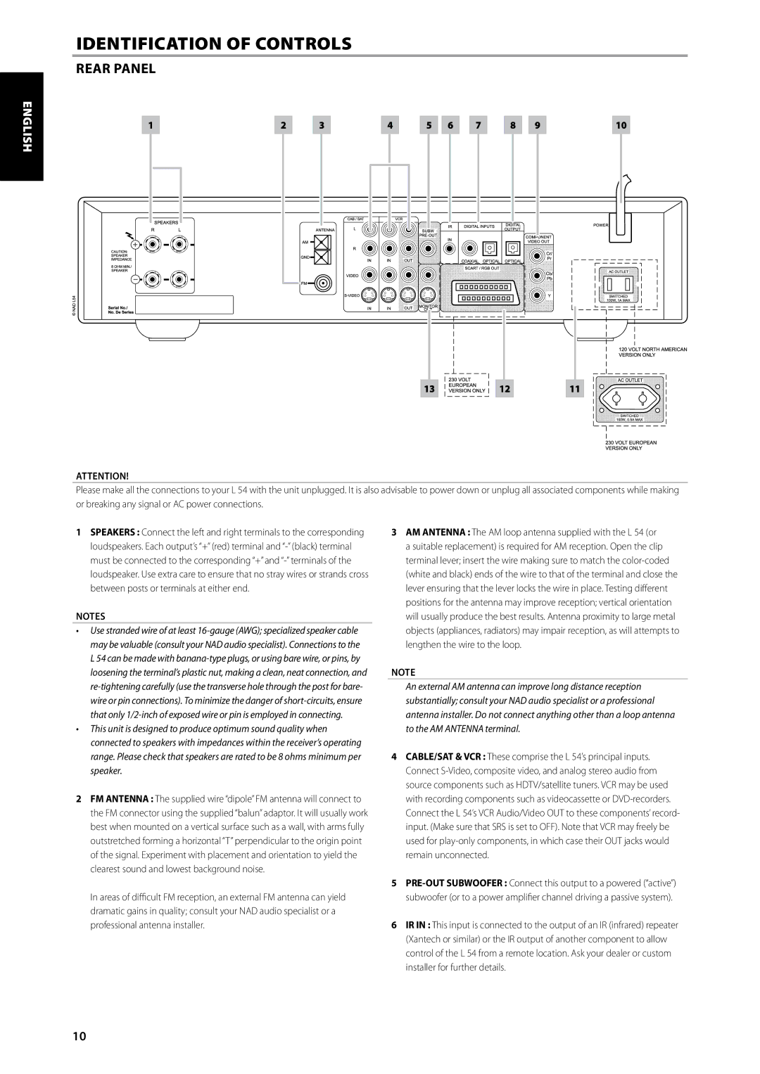
REAR PANEL
1 | 2 | 3 | 4 | 5 | 6 | 7 | 8 | 9 | 10 |
DEUTSCH NEDERLANDS
13 |
| 12 |
| 11 |
|
|
|
|
|
ATTENTION!
Please make all the connections to your L 54 with the unit unplugged. It is also advisable to power down or unplug all associated components while making or breaking any signal or AC power connections.
ESPAÑOL
ITALIANO
РУССКИЙ
SVENSKA
1SPEAKERS : Connect the left and right terminals to the corresponding loudspeakers. Each output’s “+” (red) terminal and
NOTES
•Use stranded wire of at least
•This unit is designed to produce optimum sound quality when connected to speakers with impedances within the receiver’s operating range. Please check that speakers are rated to be 8 ohms minimum per speaker.
2FM ANTENNA : The supplied wire “dipole” FM antenna will connect to the FM connector using the supplied “balun” adaptor. It will usually work best when mounted on a vertical surface such as a wall, with arms fully outstretched forming a horizontal “T” perpendicular to the origin point of the signal. Experiment with placement and orientation to yield the clearest sound and lowest background noise.
In areas of difficult FM reception, an external FM antenna can yield dramatic gains in quality; consult your NAD audio specialist or a professional antenna installer.
3AM ANTENNA : The AM loop antenna supplied with the L 54 (or a suitable replacement) is required for AM reception. Open the clip terminal lever; insert the wire making sure to match the
Note
An external AM antenna can improve long distance reception substantially; consult your NAD audio specialist or a professional antenna installer. Do not connect anything other than a loop antenna to the AM ANTENNA terminal.
4CABLE/SAT & VCR : These comprise the L 54’s principal inputs. Connect
5
6IR IN : This input is connected to the output of an IR (infrared) repeater (Xantech or similar) or the IR output of another component to allow control of the L 54 from a remote location. Ask your dealer or custom installer for further details.
10