8
In the United States: While it is not required, it is recom- mended that a chimney liner be installed that is continuous from the insert to the top of the chimney, particularly when the insert is installed in a basement. For this type of connection, use the “In Canada” installation instructions above.
In the United States, continued:
If a continuous liner is not installed, a “direct flue connec- tion” must be made. The direct flue connection requires a
1402 INSERT MODEL
An optional low clearance flue connector is available to fa- cilitate hook up into a tight fitting fireplace. Consult your local dealer for details.
The following installation requirements must be observed when installing solid fuel burning inserts into factory built fireplaces.
INSTALLATION INTO A FACTORY BUILT
FIREPLACE
1. The factory built fireplace must be listed per UL 127 or |
ULC S610. |
2. Clearances to any combustible material surrounding this |
insert as identified in Figure 10 must be followed. These clear- |
ance requirements supersede any |
clearances listed for the factory built fireplace. |
3. Installation must include a full height listed chimney liner |
meeting HT requirements (2100°F) per 1777 (U.S.) or ULC |
S635 (Canada). The liner must be securely attached to the |
insert flue collar and the chimney top. |
4. Means must be provided to prevent room air passage to the |
chimney cavity of the fireplace. This may be accomplished by |
sealing the damper area around the chimney liner, or sealing |
the fireplace front. |
5. The air flow within and around the fireplace shall not be |
altered by the installation of the insert (i.e. no louvres or cool- |
ing air inlet or outlet ports are blocked), unless specifically |
tested as such for each factory built fireplace manufacturer |
and model line. (Note - using a louvred face plate (surround) |
complies with this requirement) |
6. Alteration of the fireplace in any manner is not permitted |
with the following exceptions; |
a. external trim pieces which do not affect the operation |
of the fireplace may be removed providing they can be |
stored on or within the fireplace for reassembly if the insert |
is removed. |
b. the chimney damper may be removed to install the |
chimney liner. |
7. Circulating air chambers (i.e. in a steel fireplace liner or |
metal heat circulator) shall not be blocked. |
8. Means must be provided for removal of the insert to clean |
the chimney flue. |
9. Inserts that project in front of the fireplace must be supplied |
OPTIONAL BLOWER
Drywall dust will penetrate into the blower bearings, causing irreparable damage. Care must be taken to prevent drywall dust from coming into contact with the blower or its compartment. Any damage resulting from this condition is not covered by the warranty policy.
Use of the blower increases the output of
heat.
STOVE MODELS
Provisions have been made on the stove to install an optional blower kit
LEG MODELS ONLY
NOTE: if the optional blower
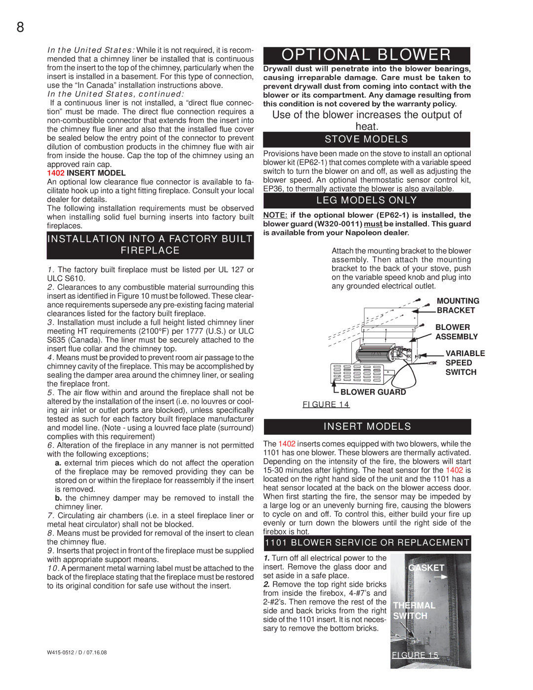
Attach the mounting bracket to the blower assembly. Then attach the mounting bracket to the back of your stove, push on the variable speed knob and plug into any grounded electrical outlet.
MOUNTING
![]()
![]() BRACKET
BRACKET
BLOWER
![]()
![]()
![]()
![]()
![]()
![]()
![]()
![]()
![]()
![]() ASSEMBLY
ASSEMBLY
![]()
![]()
![]()
![]()
![]()
![]()
![]()
![]()
![]()
![]()
![]()
![]()
![]()
![]() VARIABLE
VARIABLE
SPEED
SWITCH
![]() BLOWER GUARD
BLOWER GUARD
FIGURE 14
INSERT MODELS
The 1402 inserts comes equipped with two blowers, while the 1101 has one blower. These blowers are thermally activated. Depending on the intensity of the fire, the blowers will start
1101 BLOWER SERVICE OR REPLACEMENT
with appropriate support means. |
10. A permanent metal warning label must be attached to the |
back of the fireplace stating that the fireplace must be restored |
to its original condition for safe use without the insert. |
1.Turn off all electrical power to the insert. Remove the glass door and set aside in a safe place.
2.Remove the top right side bricks from inside the firebox,
GASKET
THERMAL SWITCH
FIGURE 15 | |
|