OPERATION
FIGURE C
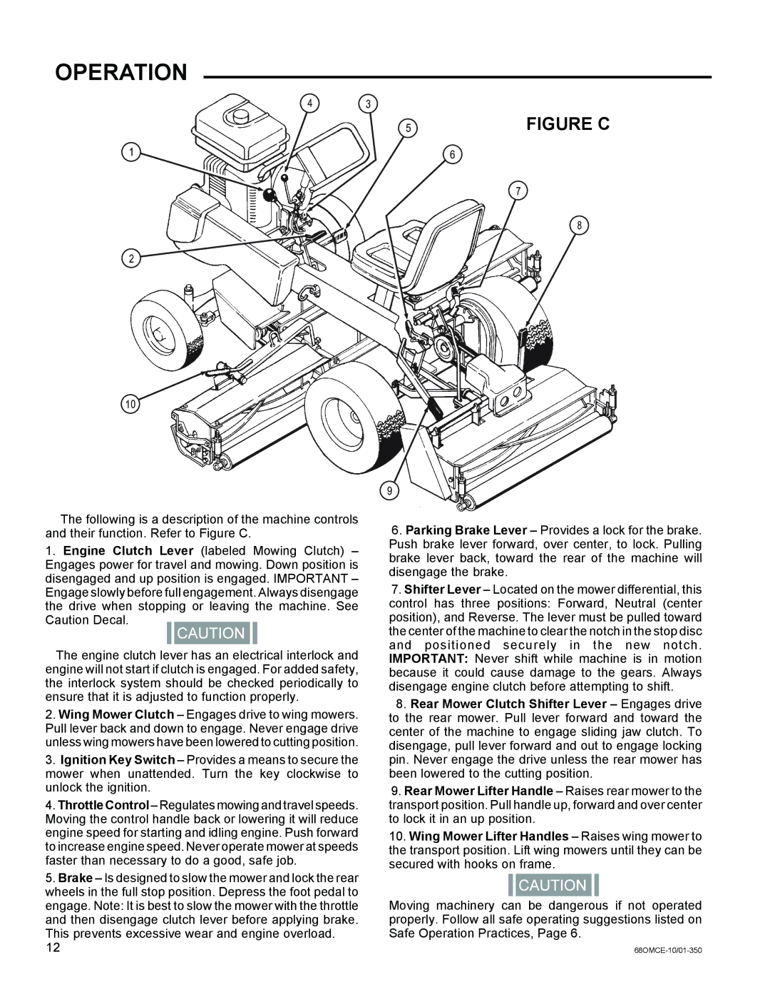
The following is a description of the machine controls and their function. Refer to Figure C.
1.Engine Clutch Lever (labeled Mowing Clutch) – Engages power for travel and mowing. Down position is disengaged and up position is engaged. IMPORTANT – Engage slowly before full engagement. Always disengage the drive when stopping or leaving the machine. See Caution Decal.
The engine clutch lever has an electrical interlock and engine will not start if clutch is engaged. For added safety, the interlock system should be checked periodically to ensure that it is adjusted to function properly.
2.Wing Mower Clutch – Engages drive to wing mowers. Pull lever back and down to engage. Never engage drive unless wing mowers have been lowered to cutting position.
3.Ignition Key Switch – Provides a means to secure the mower when unattended. Turn the key clockwise to unlock the ignition.
4.Throttle Control – Regulates mowing and travel speeds. Moving the control handle back or lowering it will reduce engine speed for starting and idling engine. Push forward to increase engine speed. Never operate mower at speeds faster than necessary to do a good, safe job.
5.Brake – Is designed to slow the mower and lock the rear wheels in the full stop position. Depress the foot pedal to engage. Note: It is best to slow the mower with the throttle and then disengage clutch lever before applying brake. This prevents excessive wear and engine overload.
6.Parking Brake Lever – Provides a lock for the brake. Push brake lever forward, over center, to lock. Pulling brake lever back, toward the rear of the machine will disengage the brake.
7.Shifter Lever – Located on the mower differential, this control has three positions: Forward, Neutral (center position), and Reverse. The lever must be pulled toward the center of the machine to clear the notch in the stop disc and positioned securely in the new notch. IMPORTANT: Never shift while machine is in motion because it could cause damage to the gears. Always disengage engine clutch before attempting to shift.
8.Rear Mower Clutch Shifter Lever – Engages drive to the rear mower. Pull lever forward and toward the center of the machine to engage sliding jaw clutch. To disengage, pull lever forward and out to engage locking pin. Never engage the drive unless the rear mower has been lowered to the cutting position.
9.Rear Mower Lifter Handle – Raises rear mower to the transport position. Pull handle up, forward and over center to lock it in an up position.
10.Wing Mower Lifter Handles – Raises wing mower to the transport position. Lift wing mowers until they can be secured with hooks on frame.
Moving machinery can be dangerous if not operated properly. Follow all safe operating suggestions listed on Safe Operation Practices, Page 6.