Manuals
/
NEC
/
Computer Equipment
/
Laptop
NEC
M7, M5
manual
Dipswitch Settings, Screws
Models:
M7
M5
1
27
28
28
Download
28 pages
45.05 Kb
21
22
23
24
25
26
27
28
Disconnecting LCD Connector
Disassembly Instructions
Removing the Battery
Dipswitch Settings
Power Supply Unit
Page 27
Image 27
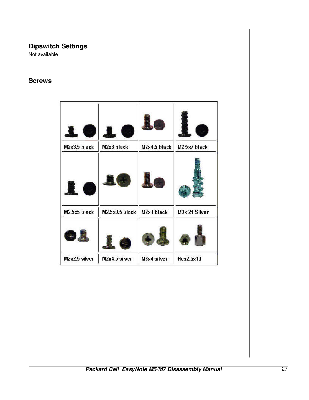
Dipswitch Settings
Not available
Screws
Packard Bell EasyNote M5/M7 Disassembly Manual
27
Page 26
Page 28
Page 27
Image 27
Page 26
Page 28
Contents
Packard Bell EasyNote M5 / M7 Disassembly Manual
Table of contents
Technician Notes
Disassembly Instructions
Reassembly Instructions
Overview
Power Supply Unit
Hazardous Voltage
Avoid Electrostatic Discharge
Removing the Battery
Removing the Hard Disk Drive
=M2.5x7 black =M2.5x5 black
M3x4 silver
Disconnecting the hard disk drive
M2.5x5 black
Removing the Optical Disk Drive
M2x2.5 silver
Removing the Keyboard
Unlock the Keyboard
Removing the screw retaining the memory module slot cover
Removing the Memory Module
Removing the LCD Module
Disconnecting LCD Connector
M3x6 silver
Removing the 15 LCD Panel
=M2x4 black =M2.5x7 black
Screws on the LCD Module
=M2.5x7 black =M2x4 black
Removing the LCD panel screws
M2x3.5 black
Removing the 14 LCD Panel
Unscrew all screws as shown in Fig
=M2x4.5 Silver =M2x4 black =M2.5x7 black
Removing the side rubber covers
M2x3.5 black M2.5x5 black
Removing the CPU
M3x21
Removing the heat sink
Removing the Quick Key Board
Removing the Bottom Cover
=M2.5x7 black =M2.5x5 black =M2.5x3.5 Black =Hex2.5x10
Removing screws on bottom of the system
Removing the Bottom Cover
Removing the Main Board
Disconnecting main board and LED board
M2.5x7 black M2x4.5 black
Removing the MDC Modem Module
Removing the Wlan Module
Removing the Wlan Module
Removing the Speaker Assembly
Removing the Touch Pad
M2x3 black M2x3.5 black
Screws
Dipswitch Settings
EasyNote M5/M7 Disassembly Manual
Top
Page
Image
Contents