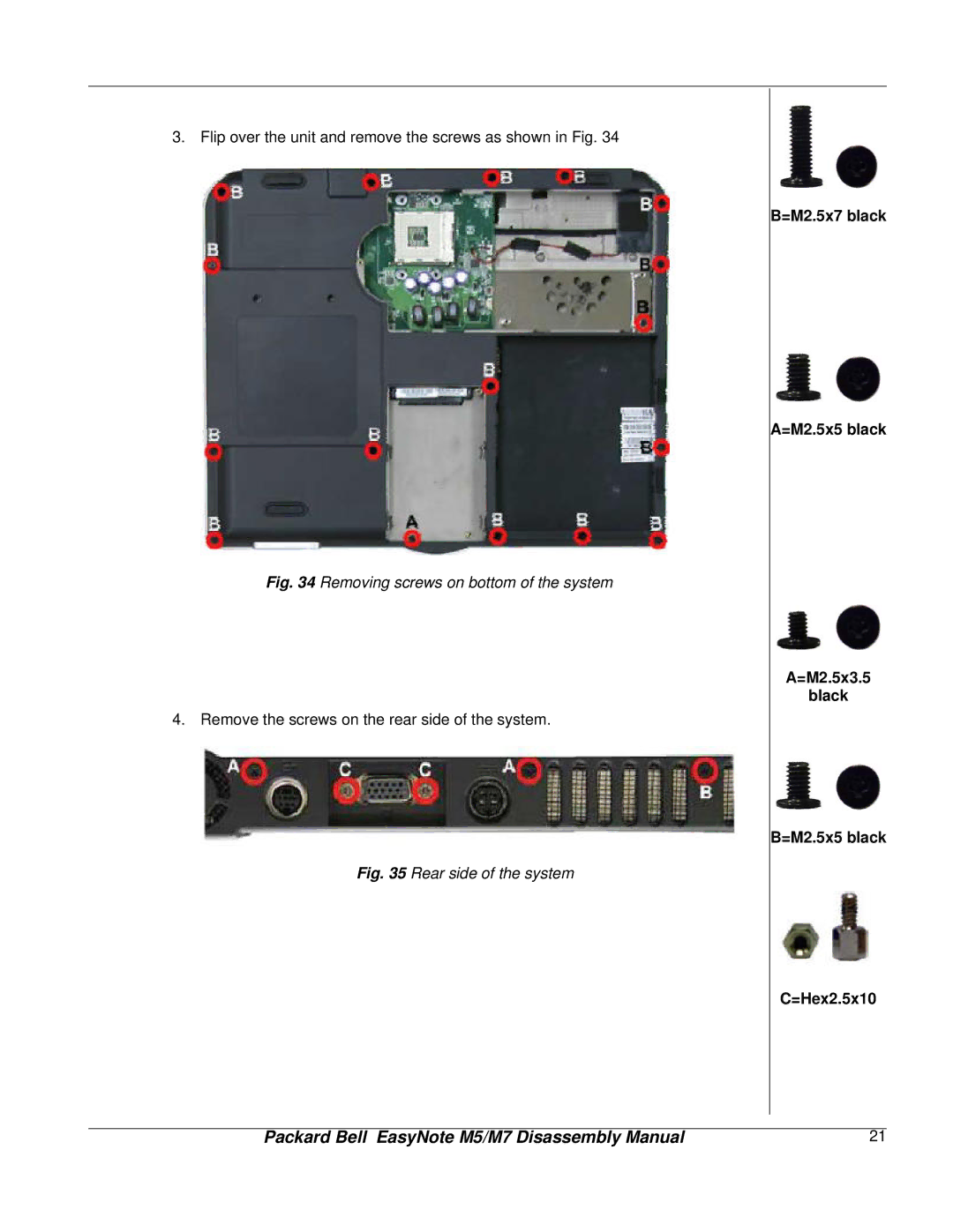
3. Flip over the unit and remove the screws as shown in Fig. 34
Fig. 34 Removing screws on bottom of the system
4.Remove the screws on the rear side of the system.
Fig. 35 Rear side of the system
B=M2.5x7 black
A=M2.5x5 black
A=M2.5x3.5
black
B=M2.5x5 black
C=Hex2.5x10
Packard Bell EasyNote M5/M7 Disassembly Manual | 21 |
