Connecting Port | Connecting Device | Cable Used | |
on the Hub | |||
|
| ||
|
|
| |
Model EN104 hub: |
|
| |
Ports | PC, server, or router | ||
Ports | Hub or switch | Crossover cable | |
|
|
| |
Model EN108 hub: |
|
| |
Ports | PC, server, or router | ||
Ports | Hub or switch | Crossover cable | |
|
|
| |
Model EN116 hub: |
|
| |
Ports | PC, server, or router | ||
Ports | Hub or switch | Crossover cable | |
|
|
|
Set the Normal/Uplink Push Button
If you are connecting to port 4 on the Model EN104 hub, port 8 on the Model EN108 hub, or port 16 on the Model EN116 hub, use the following table. Determine the type of cable to use and how to set the Normal/Uplink push button.
Connecting Port | Connecting Device | Cable Used |
|
|
|
Port 4, port 8, or port 16 | PC, server, or router | |
set to Normal |
|
|
|
|
|
Port 4, port 8, or port 16 | Hub or switch | |
set to Uplink |
|
|
|
|
|
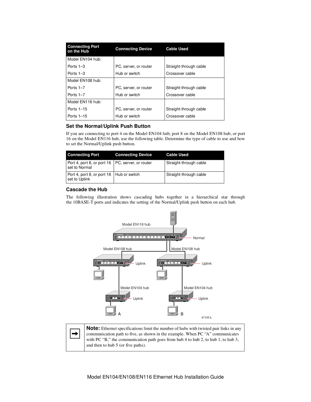
Cascade the Hub
The following illustration shows cascading hubs together in a hierarchical star through the
| Model EN116 hub |
|
|
|
|
|
|
|
| |||||||
Pwr |
|
| EN116 |
|
|
|
|
|
|
|
|
|
|
| LINK | Rx |
|
|
|
|
|
|
|
|
|
|
|
|
|
|
| Normal | |
Col |
|
|
|
|
|
|
|
|
|
|
|
|
|
|
| |
1 | 2 | 3 | 4 | 5 | 6 | 7 | 8 | 1 | 2 | 3 | 4 | 5 | 6 | 7 | 8 | |
Model EN108 hub | Model EN108 hub |
Pwr |
|
| EN108 |
|
|
|
|
| Pwr |
|
| EN108 |
|
|
|
|
|
|
|
|
|
|
|
| Uplink |
|
|
|
|
|
|
| Uplink | ||
Col |
|
|
|
|
|
|
| Col |
|
|
|
|
|
|
| ||
1 | 2 | 3 | 4 | 5 | 6 | 7 | 8 | 1 | 2 | 3 | 4 | 5 | 6 | 7 | 8 |
Model EN104 hub | Model EN104 hub |
Uplink | Uplink |
A | B |
| 8735FA |
Note: Ethernet specifications limit the number of hubs with twisted pair links in any communication path to five, as shown in the example. When PC “A” communicates with PC “B,” the communication path goes from hub 4 to hub 2, to hub 1, to hub 3, and then to hub 5 (or five paths).
Model EN104/EN108/EN116 Ethernet Hub Installation Guide