The following illustration shows cascading hubs together
Model EN104 hub
|
|
|
| 10 |
|
| |
|
| Pwr |
|
| LINK | Rx |
|
|
| Col |
|
|
|
|
|
Model EN108 hub |
|
| |||||
Pwr |
| 10 |
|
|
| LINK | Rx |
|
|
|
|
|
|
| |
Col |
|
|
|
|
|
|
|
1 | 2 | 3 | 4 | 5 | 6 | 7 | 8 |
Normal
Uplink
|
|
|
|
| Model EN116 hub |
|
|
|
|
|
|
|
|
|
|
|
|
|
|
|
|
|
|
|
| |||||||||||||
|
|
|
|
|
|
|
|
|
|
|
|
|
|
|
|
|
|
|
|
|
|
|
|
|
|
|
|
|
|
|
|
|
|
|
|
|
|
|
Pwr |
|
|
| 10 |
|
|
|
|
|
|
|
|
|
|
|
|
|
|
|
|
|
|
|
|
|
|
|
|
| LINK |
| Rx |
|
| ||||
|
|
|
|
|
|
|
|
|
|
|
|
|
|
|
|
|
|
|
|
|
|
|
|
|
|
|
|
|
|
|
|
|
|
|
|
|
| |
Col |
|
|
|
|
|
|
|
|
|
|
|
|
|
|
|
|
|
|
|
|
|
|
|
|
|
|
|
|
|
|
|
|
|
|
|
|
|
|
1 | 2 | 3 |
| 4 |
| 5 | 6 | 7 | 8 |
| 1 | 2 | 3 | 4 |
| 5 | 6 | 7 |
| 8 |
|
|
|
| ||||||||||||||
|
|
|
|
|
|
|
|
|
|
|
|
|
|
|
|
|
|
|
|
|
|
|
|
|
|
|
|
|
|
|
|
|
|
|
|
|
|
|
Uplink
8733FA
Connect to a Network Using the BNC Port
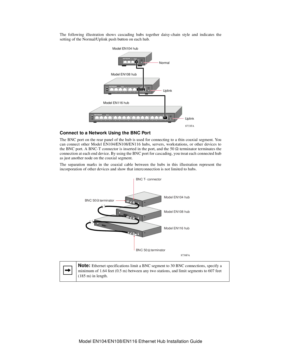
The BNC port on the rear panel of the hub is used for connecting to a thin coaxial segment. You can connect other Model EN104/EN108/EN116 hubs, servers, workstations, or other devices to the BNC port. A
The separation marks in the coaxial cable between the hubs in this illustration represent the incorporation of other devices and show that interconnection is not limited to hubs.
BNC T- connector
Model EN104 hub
BNC 50 ![]() terminator
terminator
Model EN108 hub
Model EN116 hub
BNC 50 ![]() terminator
terminator
8736FA
Note: Ethernet specifications limit a BNC segment to 30 BNC connections, specify a minimum of 1.64 feet (0.5 m) between any two stations, and limit segments to 607 feet (185 m) in length.
Model EN104/EN108/EN116 Ethernet Hub Installation Guide