NTI UNIMUX SERIES USB DVI KVM SWITCH
1
R |
NTI |
NetworkTechnologiesInc
UNIMUXTM
Scan BroadcastCommand
| 1 | 2 | 3 | 4 |
|
|
|
| 2 |
| 3 |
| |
|
|
| ||||
4 | 5 |
|
|
| 6 |
|
|
|
|
|
| ||
|
|
|
|
|
|
|
| Monitor |
| Video4 | Video3 | Video2 | Video1 |
R NETWORK |
|
|
|
|
|
|
| |
TECHNOLOGIES |
|
|
|
|
|
|
| |
NTINCORPORATED | 5VDC | CPU4 | CPU3 | CPU2 | CPU1 | USBDevices | ||
1275DannerDr | ||||||||
+ |
|
|
|
|
|
| ||
Aurora,OH44202 www.nti1.com |
|
|
|
|
|
| ||
|
|
|
|
|
|
| ||
| - | + |
|
|
|
|
| |
7 | 8 | 9 | 10 |
FEATURES AND FUNCTIONS
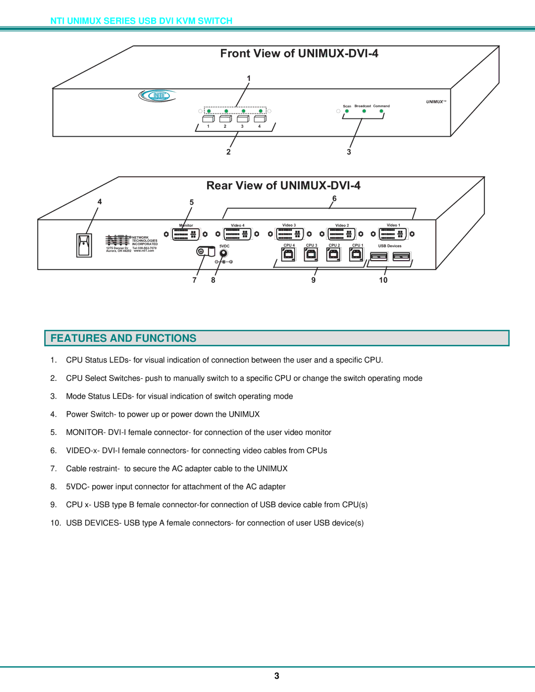
1.CPU Status LEDs- for visual indication of connection between the user and a specific CPU.
2.CPU Select Switches- push to manually switch to a specific CPU or change the switch operating mode
3.Mode Status LEDs- for visual indication of switch operating mode
4.Power Switch- to power up or power down the UNIMUX
5.MONITOR-
6.
7.Cable restraint- to secure the AC adapter cable to the UNIMUX
8.5VDC- power input connector for attachment of the AC adapter
9.CPU x- USB type B female
10.USB DEVICES- USB type A female connectors- for connection of user USB device(s)
3
