NTI UNIMUX SERIES USB DVI KVM SWITCH
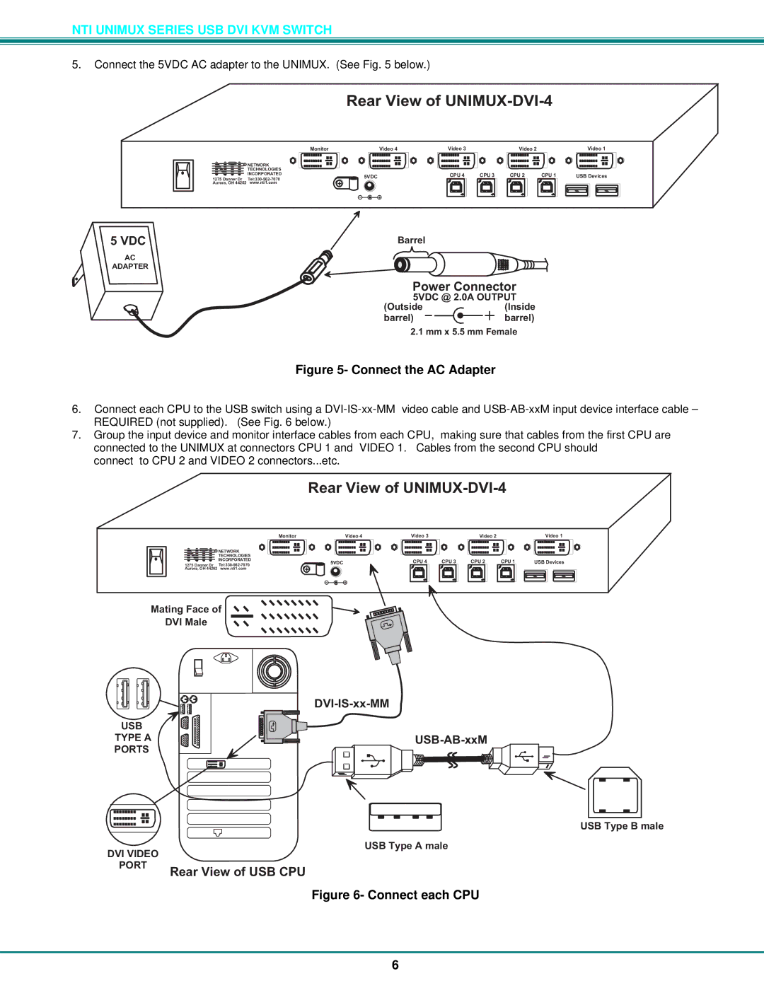
5.Connect the 5VDC AC adapter to the UNIMUX. (See Fig. 5 below.)
RearViewofUNIMUX-DVI-4
Monitor | Video4 | Video3 | Video2 | Video1 |
R NETWORK |
|
|
|
|
|
|
|
TECHNOLOGIES |
|
|
|
|
|
|
|
NTINCORPORATED | 5VDC | CPU4 | CPU3 | CPU2 | CPU1 | USBDevices | |
1275DannerDr | |||||||
Aurora,OH44202 www.nti1.com | + |
|
|
|
|
|
|
|
|
|
|
|
|
| |
| - | + |
|
|
|
|
|
5VDC | Barrel |
Adapter
AC
ADAPTER
PowerConnector
5VDC@ 2.0AOUTPUT
(Outside | (Inside |
barrel) | barrel) |
2.1mmx5.5mmFemale
Figure 5- Connect the AC Adapter
6.Connect each CPU to the USB switch using a
7.Group the input device and monitor interface cables from each CPU, making sure that cables from the first CPU are connected to the UNIMUX at connectors CPU 1 and VIDEO 1. Cables from the second CPU should
connect to CPU 2 and VIDEO 2 connectors...etc.
RearViewofUNIMUX-DVI-4
Monitor | Video4 | Video3 | Video2 | Video1 |
R NETWORK |
|
|
|
|
|
|
| |
TECHNOLOGIES |
|
|
|
|
|
|
| |
NTINCORPORATED | 5VDC | CPU4 | CPU3 | CPU2 | CPU1 | USBDevices | ||
1275DannerDr | ||||||||
+ |
|
|
|
|
|
| ||
Aurora,OH44202 www.nti1.com |
|
|
|
|
|
| ||
|
|
|
|
|
|
| ||
| - | + |
|
|
|
|
| |
MatingFaceof ![]()
![]()
DVIMale
USB
TYPEA PORTS
USBTypeBmale
USBTypeAmale
DVIVIDEO
PORT
RearViewofUSBCPU
Figure 6- Connect each CPU
6