NTI XTENDEX Wall Mount Extenders
INTERCONNECTION CABLE WIRING METHOD
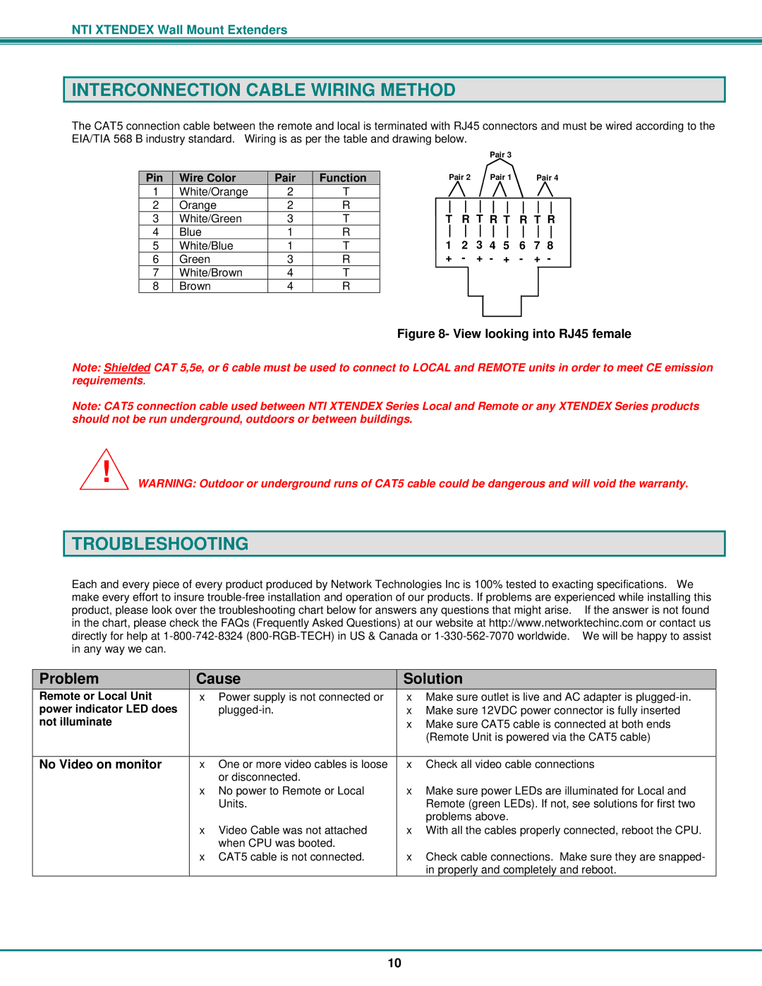
The CAT5 connection cable between the remote and local is terminated with RJ45 connectors and must be wired according to the EIA/TIA 568 B industry standard. Wiring is as per the table and drawing below.
|
|
|
|
|
|
| Pair 3 |
|
|
| |
|
|
|
|
|
|
|
|
| |||
Pin | Wire Color | Pair | Function | Pair 2 |
| Pair 1 |
| Pair 4 | |||
1 | White/Orange | 2 | T |
|
|
|
|
|
|
|
|
2 | Orange | 2 | R | T | R T R T | R T R | |||||
3 | White/Green | 3 | T | ||||||||
4 | Blue | 1 | R | 1 | 2 | 3 | 4 | 5 | 6 | 7 | 8 |
5 | White/Blue | 1 | T | ||||||||
6 | Green | 3 | R | + | - | + | - | + | - | + | - |
7 | White/Brown | 4 | T |
|
|
|
|
|
|
|
|
8 | Brown | 4 | R |
|
|
|
|
|
|
|
|
Figure 8- View looking into RJ45 female
Note: Shielded CAT 5,5e, or 6 cable must be used to connect to LOCAL and REMOTE units in order to meet CE emission requirements.
Note: CAT5 connection cable used between NTI XTENDEX Series Local and Remote or any XTENDEX Series products should not be run underground, outdoors or between buildings.
!WARNING: Outdoor or underground runs of CAT5 cable could be dangerous and will void the warranty.
TROUBLESHOOTING
Each and every piece of every product produced by Network Technologies Inc is 100% tested to exacting specifications. We make every effort to insure
Problem | Cause | Solution |
Remote or Local Unit | • Power supply is not connected or | • Make sure outlet is live and AC adapter is |
power indicator LED does | • Make sure 12VDC power connector is fully inserted | |
not illuminate |
| • Make sure CAT5 cable is connected at both ends |
|
| (Remote Unit is powered via the CAT5 cable) |
|
|
|
No Video on monitor | • One or more video cables is loose | • Check all video cable connections |
| or disconnected. |
|
| • No power to Remote or Local | • Make sure power LEDs are illuminated for Local and |
| Units. | Remote (green LEDs). If not, see solutions for first two |
|
| problems above. |
| • Video Cable was not attached | • With all the cables properly connected, reboot the CPU. |
| when CPU was booted. |
|
| • CAT5 cable is not connected. | • Check cable connections. Make sure they are snapped- |
|
| in properly and completely and reboot. |
10