NTI XTENDEX Wall Mount Extenders
Connect the CAT5 cable
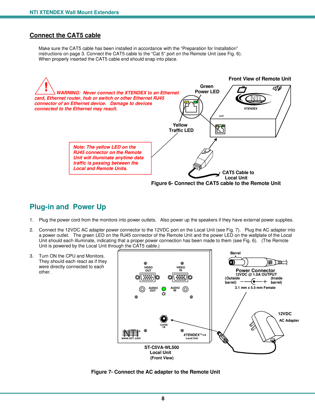
Make sure the CAT5 cable has been installed in accordance with the “Preparation for Installation” instructions on page 3. Connect the CAT5 cable to the “Cat 5” port on the Remote Unit (see Fig. 6). When properly inserted the CAT5 cable end should snap into place.
! WARNING: Never connect the XTENDEX to an Ethernet | Front View of Remote Unit |
Green | |
Power LED | |
card, Ethernet router, hub or switch or other Ethernet RJ45 | NetworkNTITechnologies Inc |
| R |
connector of an Ethernet device. Damage to devices |
|
connected to the Ethernet may result. | XTENDEX |
Yellow
Traffic LED
Note: The yellow LED on the RJ45 connector on the Remote Unit will illuminate anytime data traffic is passing between the Local and Remote Units.
 CAT5 Cable to
Local Unit
Figure 6- Connect the CAT5 cable to the Remote Unit
Plug-in and Power Up
1.Plug the power cord from the monitors into power outlets. Also power up the speakers if they have external power supplies.
2.Connect the 12VDC AC adapter power connector to the 12VDC port on the Local Unit (see Fig. 7). Plug the AC adapter into a power outlet. The green LED on the RJ45 connector of the Remote Unit and the power LED on the wallplate of the Local Unit should each illuminate, indicating that a proper power connection has been made to them (see Fig. 6). (The Remote Unit is powered by the Local Unit through the CAT5 cable.)
3.Turn ON the CPU and Monitors. They should each react as if they were directly connected to each other.
|
| Barrel |
|
VIDEO | VIDEO | Power Connector | |
OUT | IN | ||
|
| 12VDC @ 1.0A OUTPUT | |
|
| (Outside | (Inside |
|
| barrel) | barrel) |
AUDIO | AUDIO | 2.1 mm x 5.5 mm Female | |
OUT | IN |
|
|
12VDC
AC Adapter
| 12VDC |
NTI R | 1A |
XTENDEX TM VA | |
www.nti1.com | Local Unit |
Local Unit
(Front View)
Figure 7- Connect the AC adapter to the Remote Unit
8