NTI XTENDEX Wall Mount Extenders
INSTALLATION
Installing The Local Unit
Connect The CAT5 Cable
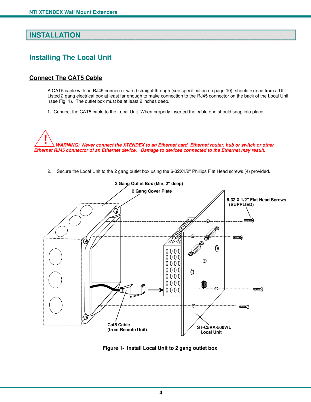
A CAT5 cable with an RJ45 connector wired straight through (see specification on page 10) should extend from a UL Listed 2 gang electrical box at least far enough to make connection to the RJ45 connector on the back of the Local Unit (see Fig. 1). The outlet box must be at least 2 inches deep.
1.Connect the CAT5 cable to the Local Unit. When properly inserted the cable end should snap into place.
!WARNING: Never connect the XTENDEX to an Ethernet card, Ethernet router, hub or switch or other Ethernet RJ45 connector of an Ethernet device. Damage to devices connected to the Ethernet may result.
2.Secure the Local Unit to the 2 gang outlet box using the
2 Gang Outlet Box (Min. 2" deep)
2 Gang Cover Plate
Cat5 Cable
(from Remote Unit)ST-C5VA-500WL
Local Unit
Figure 1- Install Local Unit to 2 gang outlet box
4