Multi-Power Battery Pack
Page
Page
Page
User’s Manual
Table of Contents
Precautions for Use
Safety Precautions
Following apply only to users European countries
MB-D12 is for use with compatible cameras only
Walt Whitman Road, Melville, New York
Nikon Inc
MB-D12 and Supplied Accessories
Introduction MB-D12 and Accessories
AFON button
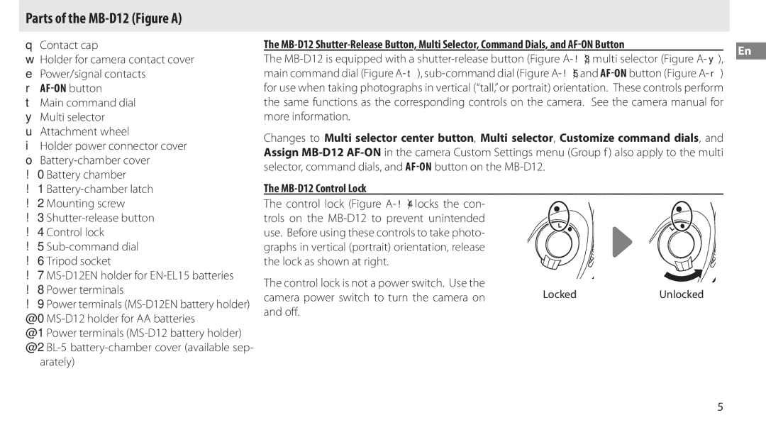
Parts of the MB-D12 Figure a
Arately
MB-D12 Control Lock
Using the Battery Pack
Attaching the Battery Pack
Removing the Battery Pack
Inserting Batteries
EP-5B Power Connector
EN-EL15/EN-EL18
Removing Batteries
Slide the battery release in the direction
EN-EL15 EN-EL18 AA Batteries
While pressing the holder Push button, slide
Power source
Weight
Specifications
Inhaltsverzeichnis
Benutzerhandbuch
Gebrauchshinweise
Sicherheitshinweise
Hinweis für Kunden in Europa
Vorsicht
Einführung
MB-D12 und Zubehör
Der MB-D12 und das im Lieferumfang enthaltene Zubehör
Komponenten des MB-D12 Abbildung a
Die Auslösesperre des MB-D12
Verwenden des Batterieteils
Anbringen des Multifunktionshandgriffs
Abnehmen des Multifunktionshandgriffs
Der Akkufacheinsatz EP-5B
Einsetzen von Akkus oder Batterien
Beschreibung
Akku-/Batteriekapazität
Mignon-Zellen Größe AA
Option
Herausnehmen der Batterien bzw. der Akkus
Mignonzellen
Nehmen Sie den Akku oder die Batterien aus dem Halter
Stromversorgung
Technische Daten
Betriebstemperatur
Gewicht
Page
Manuel d’utilisation
Table des matières
Présentation
Mesures de précaution
Précautions d’utilisation
Avis pour les clients en Europe
Avertissements à l’attention des utilisateurs américains
La MB-D12 et ses accessoires
La MB-D12 et les accessoires fournis
Présentation
Descriptif de la MB-D12 figure a
Le verrouillage de commande de la MB-D12
Utilisation de la poignée-alimentation
Montage de la poignée-alimentation
Retrait de la poignée-alimentation
Le connecteur d’alimentation EP-5B
Insertion des accumulateurs/piles
’appareil affiche le niveau de charge de la façon suivante
Charge des accumulateurs/piles
Accumulateur EN-EL15/EN-EL18
Informations de l’accumulateur
Retrait des accumulateurs/piles
Piles AA
Retirez l’accumulateur ou les piles
Caractéristiques
Dimensions L × H × P
Alimentation
Poids
Tabla de contenido
Manual del usuario
Precauciones de uso
Precauciones de seguridad
Aviso para los clientes en Europa
Precaución
Se B, según la sección 15 de las normas de la FCC
Avisos para los clientes de EE.UU
Ma canadiense ICES-003
Me à la norme NMB-003 du Canada
La MB-D12 y Accesorios suministrados
Introducción La MB-D12 y Accesorios
@0Soporte MS-D12 para baterías AA
Partes de la MB-D12 Figura a
Disponible por separado
Mación, consulte el manual de la cámara.Es
Montaje de la unidad de alimentación
Uso de la unidad de alimentación
D800
Orden en el cual las baterías se van a utilizar
El conector de alimentación EP-5B
Introducción de las baterías
Batería EN-EL15/EN-EL18
Nivel de la batería
Opción
LR6 AA alcalina Alcalina LR6 AA
EN-EL15 EN-EL18 Baterías AA
Extracción de las baterías
Al pulsar el botón PUSH, deslice la batería
Cuidado de no dejar caer las baterías al qui
Especificaciones
Fuente de alimentación
Peso
Bruksanvisning
Bruke nettadapteren EH-5a/EH-5b og
Innholdsfortegnelse
Sikkerhetsregler for bruk
Sikkerhetsregler
Melding til forbrukere i Europa
No Forsiktig
MB-D12 og ekstrautstyr
Innledning
MB-D12 og medfølgende ekstrautstyr
Bruke batteridekslet BL-5 ekstrautstyr
Kontaktlokk Holder for kameraets kontaktdeksel
Deler på MB-D12 Figur a
MB-D12s utløser, multivelger, kommandohjul og AFON-knapp
MB-D12-kontrollås
Bruke batteripakken
Feste batteripakken
Fjerne batteripakken
Strømforsyningen EP-5B
Sette inn batterier
Søker Beskrivelse
Batterinivå
Alternativ Batteritype
FR6 AA litium
AA-batterier
Ta ut batterier
Strømkilde
Spesifikasjoner
Brukstemperatur
Vekt
Page
Användarhandbok
Innehållsförteckning
Avtryckaren MB-D12, multiväljaren
Försiktighetsåtgärder
Säkerhetsföreskrifter
Meddelande till kunder i Europa
Varning
MB-D12 och tillbehör
Introduktion
MB-D12 och medföljande tillbehör
Ten EP-5B säljs separat
Delarna på MB-D12 Figur a
Ström/signalkontakter r AFON-knapp
Kontaktskydd Hållare för kamerakontaktskyddet
MB-D12 Knapplås
Använda batteripacket
Sätta fast batteripacket
Ta ur batteripacket
Strömkontakten EP-5B
Sätta i batterier
Beskrivning
EN-EL15/EN-EL18-batteri
Alternativ Batterityp
AA alkaline LR6
Teriet kan sedan tas ut som fi guren visar Dem ur hållaren
Ta ur batterierna
Ta ut batterierna som visas. Var försiktig så
Att du inte tappar batterierna när du tar ut
Specifikationer
Strömkälla
Vikt
Page
Sisällysluettelo
Käyttöohje
Varo-ohjeet käyttöä varten
Turvallisuusohjeet
Huomautus eurooppalaisille asiakkaille
Varoitus
MB-D12 ja varusteet
Käyttöönotto
MB-D12 ja mukana toimitetut varusteet
Valinnaisen BL-5-akkutilan kannen käyttö
MB-D12-sovittimen varmuuslukko
MB-D12-sovittimen osat kuva a
Lukittu
Virta-/signaaliliitännät r AFON-painike
Virtalähdesovittimen käyttö
Virtalähdesovittimen liittäminen
Virtalähdesovittimen poistaminen
EP-5B Virtaliitäntä
Akkujen tai paristojen asettaminen paikalleen
Raustasonkuvake. Lisätietoja löydät kameran Ohjeesta
AA-paristot
Akkujen poistaminen
Poista paristot kuvan osoittamalla tavalla
Varo, ettet pudota paristoja, kun poistat ne
Virtalähde
Tekniset tiedot
Käyttölämpötila
Ulkomitat L × S × K
Page
Оглавление
Руководство пользователя
Примечание для пользователей в Европе
Внимание
Данное изделие предназначено
Рукоятка MB-D12 и аксессуары
Введение
Рукоятка MB-D12 и прилагаемые аксессуары
Для батарей EN-EL15 для батарей AA
Блокировочный переключатель MB-D12
Компоненты рукоятки MB-D12 Рисунок a
Использование многофункциональной рукоятки
Присоединение многофункциональной рукоятки
Извлечение рукоятки
Разъем питания EP-5B
Установка батарей
Батарея EN-EL15/EN-EL18
Уровень заряда батареи
Извлекайте батареи, когда MB-D12 не исполь- зуется
Информация о батарее
Батареи AA
Извлечение батарей
Источник питания
Технические характеристики
Рабочая температура
Размеры Ш × В × Г
Page
Indholdsfortegnelse
Brugervejledning
Anvendelse af det ekstra
Kommandohjul og AFON-knap MB-D12-knaplåsen
Forholdsregler for anvendelse
Sikkerhedsforskrifter
Bemærkning til kunder i Europa
Dukt skal indleveres separat
MB-D12 og tilbehør
Indledning
MB-D12 og medfølgende tilbehør
Gervejledning for detaljer
Komponenter på MB-D12 Figur a
Strøm-/signalkontakter r Knappen AFON
Kontaktdæksel Holder til kameraets kontaktdæksel
@2 BL-5 batterikammerdæksel forhandles se- parat
Anvendelse af batteriet
Montering af batteriet
Fjernelse af batteriet
EP-5B-stikket
Isætning af batterier
Søger Beskrivelse
Batteriniveau
Valgmulighed Batteritype LR6 AA alkalisk
Batterioplysninger
EN-EL15 EN-EL18 AA-batterier
Fjernelse af batterier
Skal du skubbe batteriet hen mod knappen
Batteriet kan så fj ernes som vist Deren
Driftstemperatur
Mål B × H × D
Vægt
Page
Inhoudsopgave
Gebruikshandleiding
Veiligheidsmaatregelen
Mededeling voor Europese klanten
Waarschuwing
MB-D12 en meegeleverde accessoires
MB-D12 en accessoires
Inleiding
De handleiding van de camera voor details
MB-D12 Bedieningsvergrendeling
Afdekkapje
Houder voor contactdeksel van de camera
Deksel van batterijvak !0 Batterijvak
Het battery pack aansluiten
Het battery pack gebruiken
Verwijder het afdekkapje fi guur A- q van het battery pack
Het battery pack verwijderen
De EP-5B stroomaansluiting
Batterijen plaatsen
EN-EL15/EN-EL18 batterij
Batterijniveau
Beschrijving
Batterijinformatie
AA-batterijen
De batterijen verwijderen
Voeding
Specificaties
Page
Manual do utilizador
Índice
Colocar a Unidade de alimentação
Precauções de utilização
Precauções de segurança
Aviso para clientes na Europa
Atenção
MB-D12 e os acessórios
Introdução
MB-D12 e os acessórios fornecidos
Bateria
Tampa do conector de alimentação do su- porte
Partes do MB-D12 Figura a
MB-D12 Travão de comando
Multisselector u Roda de encaixe
Utilizar a Unidade de alimentação
Colocar a Unidade de alimentação
Retirar a Unidade de alimentação
Conector de alimentação EP-5B
Colocar baterias
Bateria EN-EL15/EN-EL18
Nível de carga da bateria
Retire as baterias quando não estiver a utilizar o MB-D12
Informações da bateria
Baterias AA
Retirar as baterias
Especificações
Page
Sommario
Manuale d’uso
Precauzioni per l’uso
Precauzioni inerenti la sicurezza
Avviso per gli utenti europei
Attenzione
Multi power battery pack MB-D12 e accessori in dotazione
Multi power battery pack MB-D12 e accessori
Introduzione
Vedere il manuale della fotocamera
Copricontatto
Parti del multi power battery pack MB-D12 Figura a
MB-D12 Blocco dei comandi
Bloccato
Collegamento del battery pack
Utilizzo del battery pack
Rimuovere il copricontatto Figura A- q dal battery pack
Rimozione del battery pack
Connettore di alimentazione EP-5B
Inserimento delle batterie
Batteria EN-EL15/EN-EL18
Livello della batteria
Mirino Descrizione
Opzione
Batterie AA
Rimozione delle batterie
Caratteristiche
Page
Πίνακας περιεχομένων
Εγχειρίδιο οδηγιών χρήσης
Προφυλάξεις Ασφαλείας Προφυλάξεις ως προς τη Χρήση
Όσους χρησιμοποιούν το προϊόν
Σημειώσεις για τους Πελάτες στην Ευρώπη
Το MB-D12 και Εξαρτήματα
Εισαγωγή
Το MB-D12 και Παρεχόμενα Εξαρτήματα
Χανής
Το Κλείδωμα Χειριστηρίου του MB-D12
Μέρη του MB-D12 Εικόνα Α
Χρήση του Τροφοδοτικού Μπαταρίας
Σύνδεση του Τροφοδοτικού Μπαταρίας
Αφαίρεση του Τροφοδοτικού Μπαταρίας
Ακροδέκτης Τροφοδοσίας ΕΡ-5Β
Εισαγωγή Μπαταριών
Επιλογή
Επίπεδο Φορτίου Μπαταρίας
LR6 AA alkaline
Πληροφορίες Μπαταρίας
Μπαταρίες ΑΑ
Αφαίρεση των Μπαταριών
Τεχνικά χαρακτηριστικά
Πηγή τροφοδοσίας
Βάρος
Page
Spis treści
Instrukcja obsługi
Które korzystają z tego produktu
Zasady bezpieczeństwa
Uwaga dla klientów w Europie
Ostrzeżenie
Pojemnik MB-D12 i akcesoria
Wprowadzenie
Pojemnik MB-D12 i akcesoria w komplecie
Korzystanie z opcjonalnej pokrywy komory akumulatora BL-5
Koszyk MS-D12EN na baterie EN-EL15 !8 Styki zasilania
Osłona styków Uchwyt osłony styków aparatu
Dostępna osobno
Elementy pojemnika MB-D12 rysunek a
Korzystanie z pojemnika na baterie
Mocowanie pojemnika na baterie
Zdejmowanie pojemnika na baterie
Złącze zasilania EP-5B
Wkładanie baterii/akumulatorów
Akumulator EN-EL15/EN-EL18
Stan baterii
Opis
Opcja
Uważaj, aby nie upuścić baterii lub koszyka
Wyjmowanie baterii/akumulatorów
Wyjmij akumulator lub baterie z koszyka
Baterie AA
Zasilanie
Dane techniczne
Temperatura pracy
Masa
Page
Návod k obsluze
Obsah
Dodávané příslušenství
Informace k použití
Bezpečnostní upozornění
Cz vají
Upozornění pro zákazníky v Evropě
Příslušenství pro MB-D12
Úvod
Ním a pomocným příkazovým voličem pro
Použití volitelné krytky prostoru pro baterii BL-5
Krytka kontaktů
Části MB-D12 Obrázek a
Samostatně
Aretace ovladačů na MB-D12
Nasazení zařízení Battery Pack
Použití zařízení Battery Pack
Sejmutí zařízení Battery Pack
Krytku kontaktů na MB-D12
Konektor pro připojení síťového zdroje EP-5B
Vložení baterií
Baterie EN-EL15/EN-EL18
Stav baterie
Popis
Nízká kapacita baterie
Posuňte aretaci baterie ve směru vyobraze
Vyjmutí baterií
Na držáku stiskněte tlačítko Push a zároveň
Baterie vyjměte vyobrazeným způsobem
Zdroje energie
Specifikace
Provozní teplota
Rozměry š×v×h
Page
Tartalomjegyzék
Használati útmutató
Biztonsági előírások Használati előírások
Hu Megjegyzések európai vásárlóink számára
Figyelem
Az MB-D12 és tartozékai
Bevezetés
Az MB-D12 és a szállított tartozékai
Külön megvásárolható BL-5 akkumulátorfedél hasz- nálata
Érintkező sapka
Az MB-D12 részei a ábra
Az MB-D12 vezérlő zárja
Gép be- és kikapcsolásához
Az elemtartó használata
Az elemtartó csatlakoztatása
Az elemtartó eltávolítása
Az alábbiak szerint készítse elő az elemeket
Elemek behelyezése
Az EP-5B tápcsatlakozó
Fordítsa el az MB-D12 akkurögzítő zárat
EN-EL15/EN-EL18 Akkumulátor
Akkumulátor töltöttségi szintje
Beállítás
Akkumulátor adatai
Az akkumulátor eltávolítása
Hu EN-EL15
AA elemek
Műszaki adatok
Tápellátás
Tömeg
Page
Použitie voliteľného krytu priestoru pre
Užívateľská príručka
Upozornenia pri používaní
Bezpečnostné upozornenia
Poznámky pre užívateľov v Európe
Sk Pozor
Battery pack MB-D12 a príslušenstvo
Battery pack MB-D12 a dodané príslušenstvo
Formácie nájdete v príručke k fotoaparátu
Ovládacia poistka battery pack-u MB-D12
Pripojenie battery pack-u
Používanie battery pack-u
Odpojenie battery pack-u
Ak chcete odpojiť battery pack MB-D12, vy
Napájací konektor EP-5B
Vkladanie batérií
Úroveň nabitia batérie
Ak sa battery pack MB-D12 nepoužíva, vyberte batérie
Fotoaparát zobrazuje úroveň nabitia batérie takto
Batéria EN-EL15/EN-EL18
Batéria EN-EL15 Batéria EN-EL18 Batérie AA
Vyberanie batérií
Podržte tlačidlo zásobníka Push stlačené
Páčku na uvoľnenie batérie posuňte v smere
Technické parametre
Zdroj energie
Hmotnosť
Page
Kazalo vsebine
Navodila za uporabo
Varnostni ukrepi za uporabo
Varnostni ukrepi
Obvestila za stranke v Evropi
Previdno
MB-D12 in dodatna oprema
Uvod
MB-D12 in priložena dodatna oprema
EH-5b in električnega priključka EP-5B
MB-D12 kontrolni zaklep
Deli MB-D12 slika a
Kontrolni zaklep ni stikalo za vklop/izklop. Za
Vklop/izklop napajanja uporabite stikalo foto Aparata
Uporaba baterijskega napajalnika
Priključitev baterijskega napajalnika
Odstranjevanje baterijskega napajalnika
Električni priključek EP-5B
Vstavljanje baterij
Stanje baterije
MB-D12 battery type
Baterija EN-EL15/EN-EL18
Baterija je polna
Baterije AA
Odstranjevanje baterij
Odstranite baterije, kot je prikazano. Pazite
Da vam baterije ne padejo, ko jih odstranju
Vir napajanja
Tehnični podatki
Mere Š × V × G
Teža
Page
Kasutusjuhend
Akukomplekt
Kasutuse ettevaatusabinõud
Ettevaatusabinõud
Teated Euroopa klientidele
Hoiatus
MB-D12 ja tarvikud
Sissejuhatus
MB-D12 ja kaasasolevad tarvikud
Valikulise akupesa katte BL-5 kasutamine
Kontakti kate
MB-D12 osad joonis a
AFON nupp
MB-D12 nuppude lukk
Akukomplekti kasutamine
Akukomplekti kinnitamine
Akukomplekti eemaldamine
Akude paigaldamine
Nähtaval
EP-5B toitepistmik
EN-EL15/EN-EL18 aku
Akutase
Kirjeldus
Aku on täielikult
EN-EL15 EN-EL18 AA akud
Akude eemaldamine
Eemaldage akud nagu näidatud. Olge ette
Vaatlikud, et mitte pillata akusid nende ee
Toiteallikas
Tehnilised andmed
Töötemperatuur
Kaal
Page
Satura rādītājs
Lietošanas rokasgrāmata
Paziņojumi pircējiem Eiropā
Drošības pasākumi
Uzmanīgi
Šis simbols norāda, ka šis produkts ir jāsavāc atsevišķi
MB-D12 un piederumi
Ievads
MB-D12 un piegādes komplektā iekļautie piederumi
Strāvas avots sīkāk par to skatiet kameras ro- kasgrāmatu
MB-D12 vadības bloķētājs
Barošanas bloka lietošana
Barošanas bloka piestiprināšana
Barošanas bloka izņemšana
Barošanas savienotājs EP-5B
Bateriju ievietošana
Akumulators EN-EL15/EN-EL18
Akumulatora līmenis
Skatu Apraksts
Opcija Bateriju tips
Akumulatora un bateriju izņemšana
EN-EL15 EN-EL18
AA tipa baterijas
Barošanas avots
Specifikācijas
Darba temperatūra
Izmēri P × a × D
Page
Turinys
Naudojimo instrukcija
Pranešimai klientams Europoje
Atsargumo priemonės
Dėmesio
Atsargumo priemonės naudojant prietaisą
MB-D12 ir priedai
Įžanga
MB-D12 ir pateikti priedai
Laikiklio dėklas
MB-D12 valdymo fiksatorius
MB-D12 dalys pav. a
Valdymo fi ksatorius nėra maitinimo jungiklis
3žUrakto atleidimo mygtukas Lt !4 Valdymo fi ksatorius
Akumuliatoriaus naudojimas
Akumuliatoriaus pritvirtinimas
Akumuliatoriaus nuėmimas
EP-5B kintamosios srovės jungtis
Akumuliatorių įdėjimas
Fotoaparate akumuliatoriaus įkrovos lygis rodo- mas taip
Akumuliatoriaus įkrovos lygis
EN-EL15/EN-EL18 akumuliatorius
AA baterijos
Akumuliatorių išėmimas
EN-EL15 EN-EL18 AA baterijos
Klės nurodyta kryptimi Y ir nuimkite aku
Maitinimo šaltinis
Techniniai duomenys
Darbinė temperatūra
Svoris
Page
MB-D12 afsmellari, fjölvirkur valtakki
Efnisyfirlit
Viðvaranir fyrir notkun
Öryggisreglur
Tilkynning til viðskiptavina í Evrópu
Varúð
MB-D12 og aukabúnaður
Inngangur
Myndavélahandbókinni. MB-D12 tekur
MB-D12 og meðfylgjandi aukabúnaður
MB-D12 stýrilás
Hluti af MB-D12 Mynd a
Festa rafhlöðubúnað á
Notkun rafhlöðubúnaðar
Rafhlöðubúnaður tekinn úr
Slökktu á myndavélinni og settu stýrilásinn
EP-5B rafmagnstengi
Setja rafhlöður í
EN-EL15/EN-EL18 rafhlaða
Hleðslustaða rafhlöðu
Lýsing
Valkostur Rafhlöðugerð
AA rafhlöður
Fjarlægja rafhlöður
Aflgjafi
Tæknilýsing
Stærðir W × H × D
Þyngd
Page
Cuprins
Manualul utilizatorului
Precauţii pentru utilizare
Prevederi de siguranţă
Avertismente pentru clienţii din Europa
Atenţie
Introducere
MB-D12 şi accesorii
MB-D12 şi accesorii furnizate
Capac de contact
Piese ale MB-D12 Figura a
Blocare control MB-D12
Blocarea controlului nu este un comutator de
Utilizarea gripului
Ataşarea gripului
Îndepărtarea gripului
Sa înainte de a întoarce zăvorul
Introducerea bateriilor
Introdusă
Conectorul de alimentare EP-5B
Acumulator EN-EL15/EN-EL18
Nivel acumulator
Opţiune Tip baterie
Informaţii acumulator
Scoaterea bateriilor
Baterii AA
Scoateţi acumulatorul sau bateriile din carcasă
Sursă de alimentare
Specificaţii
Dimensiuni L × Î × a
Greutate
Page
Посібник користувача
Зміст
Мультиселектор і диски керування на
Правила техніки безпеки Застереження щодо використання
Примітки для користувачів з Європи
Європейських країнах
Вступ
Блок MB-D12 та аксесуари
Блок MB-D12 та аксесуари з комплекту
Блокування засобів керування на блоці MB-D12
Деталі блока MB-D12 Рис. А
Використання батарейного блока
Прикріплення батарейного блока
Зняття батарейного блока
Вставлення елементів живлення
Вставлено повністю
Зєднувач живлення EP-5B
AA, лужний LR6
Параметр
AA, нікель
AA, літієвий FR6
Елементи живлення типу АА
Виймання елементів живлення
Не кидайте елементи живлення або відсік
Вийміть елементи живлення з відсіку
Джерело живлення
Технічні параметри
Робоча температура
Ширина × глибина Вага
Nikon Corporation
SB1L03P2