R E M O T E C O N T R O L A N Y W H E R E ! K I T
“TECH TIP”
Wire size is expressed by it’s AWG (American Wire Gauge) number. The lower the AWG number, the larger the wire, i.e., 20 AWG wire is physically larger
than 22 AWG.
“TECH TIP”
Make all final connec-
tions to the MSU
before connecting the power supply. This will avoid potential dam- age to components.
7
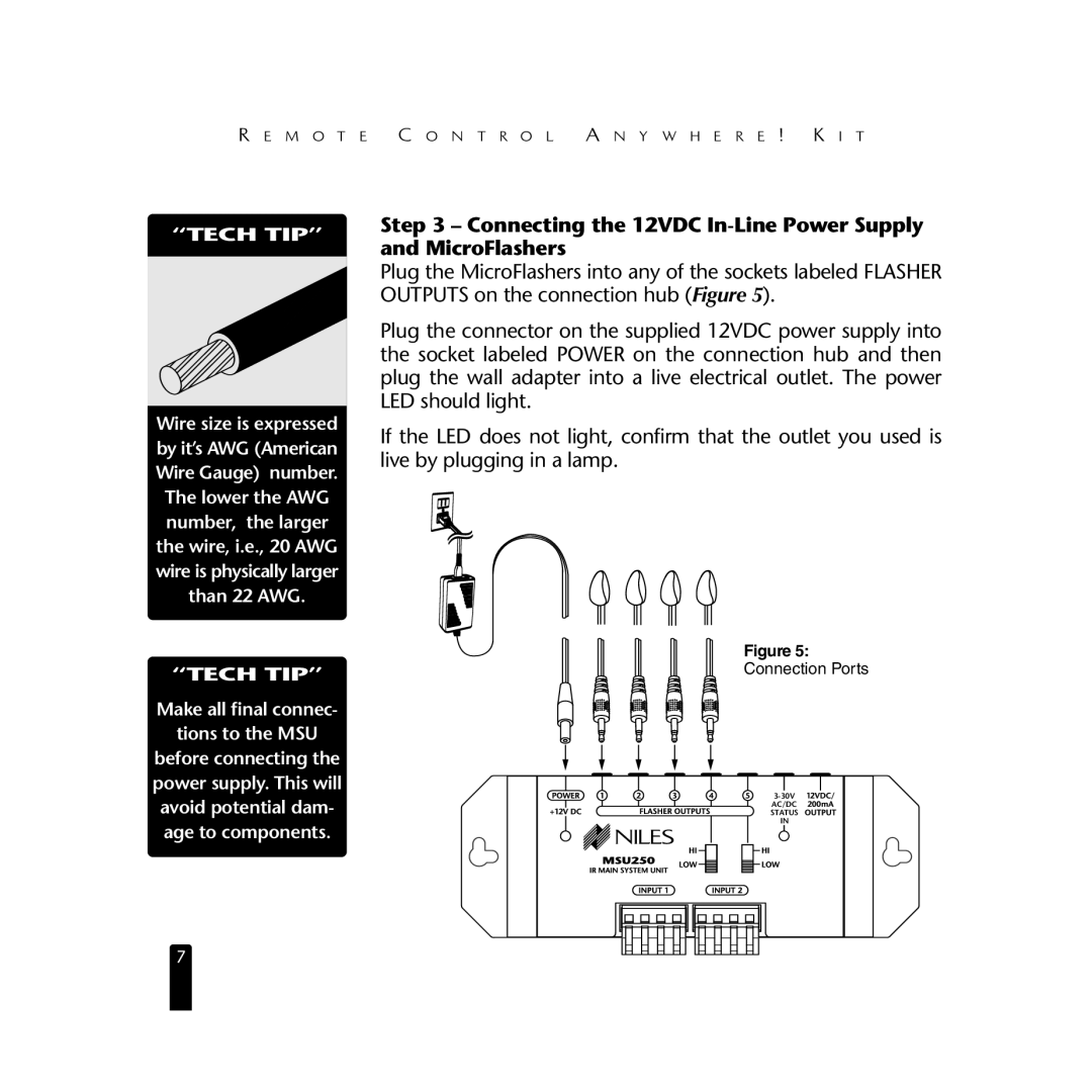
Step 3 – Connecting the 12VDC In-Line Power Supply and MicroFlashers
Plug the MicroFlashers into any of the sockets labeled FLASHER OUTPUTS on the connection hub (Figure 5).
Plug the connector on the supplied 12VDC power supply into the socket labeled POWER on the connection hub and then plug the wall adapter into a live electrical outlet. The power LED should light.
If the LED does not light, confirm that the outlet you used is live by plugging in a lamp.
Figure 5:
Connection Ports
![]()
![]() Additional
Additional
Flashers
AC/DC |
STATUS |
IN |
REMOTE CONTROL ANYWHERE! |
CONNECTION HUB |