E6581381
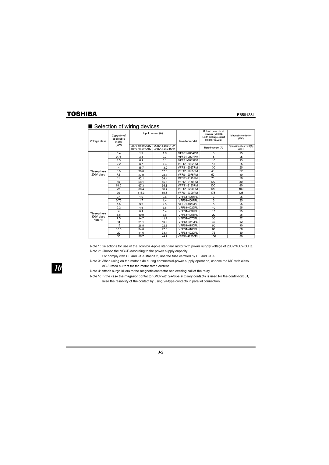
■Selection of wiring devices
|
| Input current (A) |
| Molded case circuit |
| ||
| Capacity of |
| breaker (MCCB) | Magnetic contactor | |||
|
|
|
| Earth leakage circuit | |||
| applicable |
|
|
| (MC) | ||
Voltage class |
|
| Inverter model | breaker (ELCB) | |||
motor |
|
|
| ||||
|
|
|
| ||||
| (kW) |
|
|
|
|
| |
| 200V class:200V | 200V class:240V |
| Rated current (A) | Operational current(A) | ||
|
| 400V class:380V | 400V class:480V |
| |||
|
|
|
| ||||
| 0.4 | 1.9 | 1.6 | 3 | 25 | ||
| 0.75 | 3.3 | 2.7 | 5 | 25 | ||
| 1.5 | 6.1 | 5.1 | 10 | 25 | ||
| 2.2 | 8.7 | 7.3 | 15 | 25 | ||
| 4 | 15.7 | 13.0 | 30 | 25 | ||
5.5 | 20.8 | 17.3 | 40 | 32 | |||
200V class | 7.5 | 27.9 | 23.3 | 50 | 40 | ||
| 11 | 42.1 | 34.4 | 75 | 50 | ||
| 15 | 56.1 | 45.5 | 100 | 80 | ||
| 18.5 | 67.3 | 55.8 | 100 | 80 | ||
| 22 | 80.4 | 66.4 | 125 | 100 | ||
| 30 | 113.3 | 89.5 | 175 | 125 | ||
| 0.4 | 1.0 | 0.8 | 3 | 25 | ||
| 0.75 | 1.7 | 1.4 | 3 | 25 | ||
| 1.5 | 3.2 | 2.5 | 5 | 25 | ||
| 2.2 | 4.6 | 3.6 | 10 | 25 | ||
4 | 8.1 | 6.4 | 15 | 25 | |||
5.5 | 10.9 | 8.6 | 20 | 25 | |||
400V class | |||||||
7.5 | 14.7 | 11.7 | 30 | 32 | |||
Note 4) | |||||||
11 | 21.1 | 16.8 | 40 | 32 | |||
| |||||||
| 15 | 28.5 | 22.8 | 50 | 40 | ||
| 18.5 | 34.8 | 27.8 | 60 | 50 | ||
| 22 | 41.6 | 33.1 | 75 | 80 | ||
| 30 | 56.7 | 44.7 | 100 | 80 | ||
Note 1: Selections for use of the Toshiba
Note 2: Choose the MCCB according to the power supply capacity.
For comply with UL and CSA standard, use the fuse certified by UL and CSA.
Note 3: When using on the motor side during
10
Note 4: Attach surge killers to the magnetic contactor and exciting coil of the relay.
Note 5: In the case the magnetic contactor (MC) with