E6581381
■ Power circuit
|
| Terminal symbol | Terminal function | |||||
|
|
|
|
|
|
| Grounding terminal for connecting inverter. There are 3 terminals in total. 2 terminals in | |
|
|
|
|
|
|
| the terminal board, 1 terminal in the cooling fin. | |
|
| R/L1,S/L2,T/L3 | 200V class: | |||||
|
| 400V class: | ||||||
|
|
|
|
|
|
| ||
|
| U/T1,V/T2,W/T3 | Connect to a | |||||
|
|
| ||||||
|
| PA/+, PC/- | PA/+ terminal: Positive potential terminal for the internal DC main circuit | |||||
|
| PC/- terminal: Negative potential terminal for the internal DC main circuit | ||||||
|
|
|
|
|
|
| DC power can be supplied through the PA/+ and PC/- terminals. | |
|
| The arrangement of power circuit terminals are different from each range. | ||||||
2 | ||||||||
| ⇒ See section 1.3.2.1) about the arrangement of power circuit terminals. | |||||||
| 2.3.2 | Control circuit terminals | ||||||
The control circuit terminal board is common to all equipment.
Regarding to the function and specification of each terminal, please refer to the following table.
⇒ See section 1.3.2.3) about the arrangement of control circuit terminals.
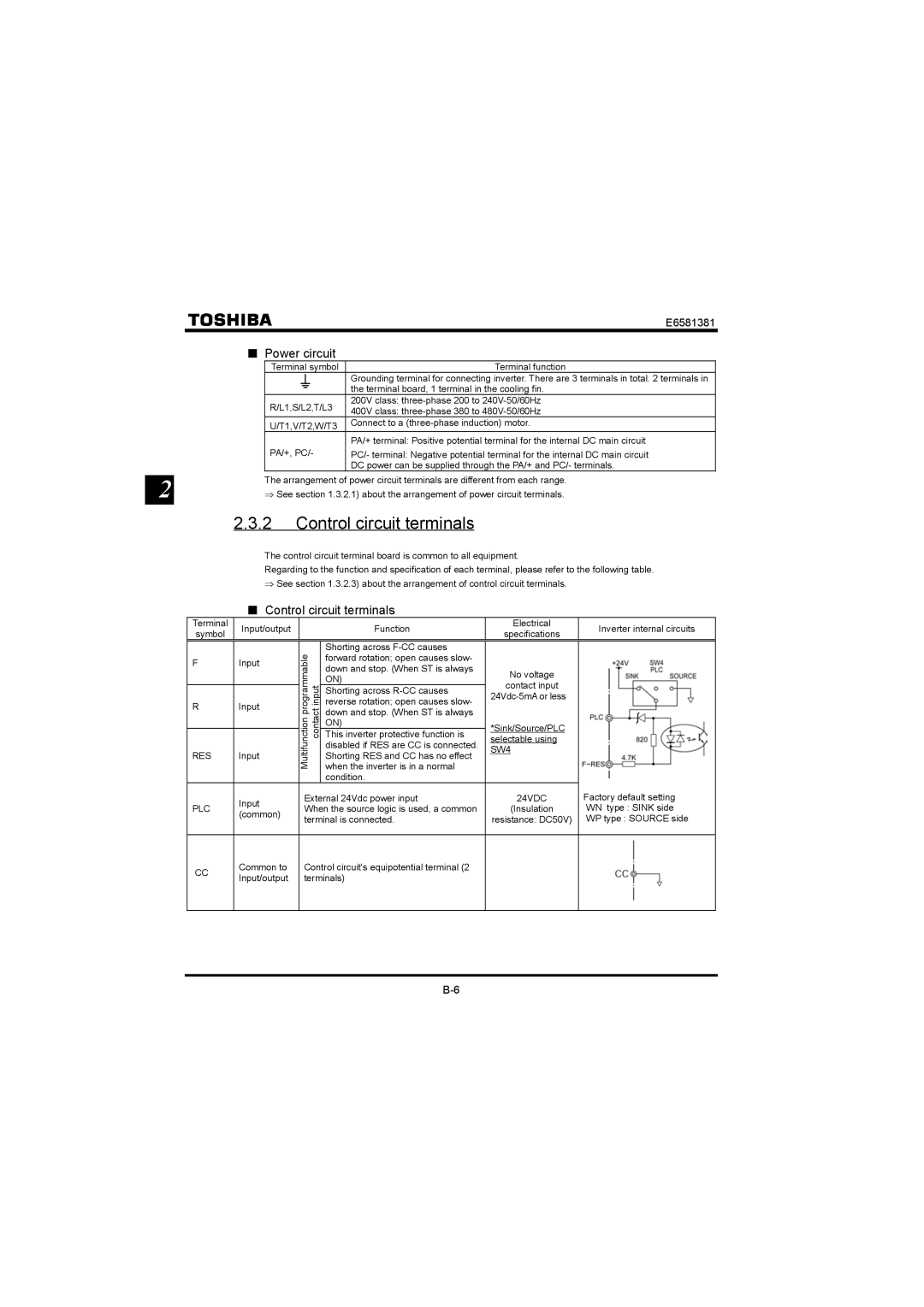
■Control circuit terminals
Terminal | Input/output |
| Function | Electrical | Inverter internal circuits | |
symbol |
| specifications | ||||
|
|
|
| |||
|
| Multifunction programmable contact input | Shorting across |
|
| |
F | Input | forward rotation; open causes slow- |
|
| ||
down and stop. (When ST is always | No voltage |
| ||||
|
|
| ||||
|
| ON) |
| |||
|
| contact input |
| |||
|
| Shorting across |
| |||
|
|
| ||||
R | Input | reverse rotation; open causes slow- |
| |||
|
| |||||
down and stop. (When ST is always |
|
| ||||
|
|
|
| |||
|
| ON) | *Sink/Source/PLC |
| ||
|
| This inverter protective function is |
| |||
|
| selectable using |
| |||
|
| disabled if RES are CC is connected. |
| |||
|
| SW4 |
| |||
RES | Input | Shorting RES and CC has no effect |
| |||
|
| |||||
|
| when the inverter is in a normal |
|
| ||
|
|
| condition. |
|
| |
| Input | External 24Vdc power input | 24VDC | Factory default setting | ||
PLC | When the source logic is used, a common | (Insulation | WN type : SINK side | |||
(common) | ||||||
| terminal is connected. | resistance: DC50V) | WP type : SOURCE side | |||
|
| |||||
|
|
|
|
| ||
CC | Common to | Control circuit's equipotential terminal (2 |
|
| ||
Input/output | terminals) |
|
| |||
|
|
| ||||
|
|
|
|
|
| |