E6581381
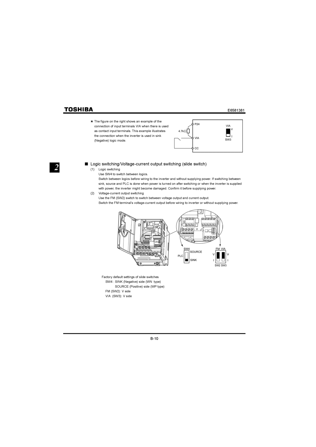
+ The figure on the right shows an example of the
| connection of input terminals VIA when there is used |
| as contact input terminals. This example illustrates |
| the connection when the inverter is used in sink |
| (Negative) logic mode. |
2 | ■ Logic |
(1) Logic switching |
Use SW4 to switch between logics.
Switch between logics before wiring to the inverter and without supplying power. If switching between sink, source and PLC is done when power is turned on after switching or when the inverter is supplied with power, the inverter might become damaged. Confirm it before supplying power.
(2)
Use the FM (SW2) switch to switch between voltage output and current output.
Switch the FM terminal's
Factory default settings of slide switches
SW4 : SINK (Negative) side (WN type)
SOURCE (Positive) side (WP type)
FM (SW2): V side
VIA (SW3): V side