E6581381
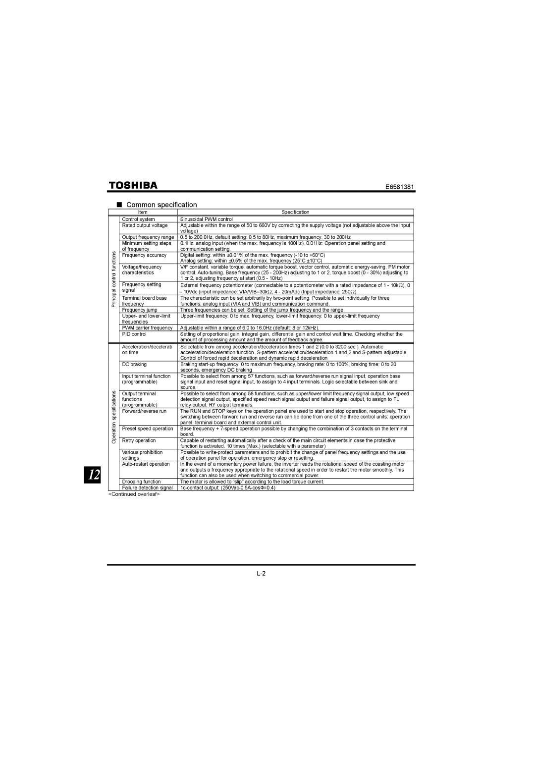
■Common specification
|
|
| Item | Specification |
|
|
| Control system | Sinusoidal PWM control |
|
|
| Rated output voltage | Adjustable within the range of 50 to 660V by correcting the supply voltage (not adjustable above the input |
|
|
|
| voltage) |
|
|
| Output frequency range | 0.5 to 200.0Hz, default setting: 0.5 to 80Hz, maximum frequency: 30 to 200Hz |
|
|
| Minimum setting steps | 0.1Hz: analog input (when the max. frequency is 100Hz), 0.01Hz: Operation panel setting and |
|
| functions | of frequency | communication setting. |
|
| Frequency accuracy | Digital setting: within ±0.01% of the max. frequency | |
|
|
| ||
|
|
|
| Analog setting: within ±0.5% of the max. frequency (25°C ±10°C) |
|
|
| Voltage/frequency | V/F constant, variable torque, automatic torque boost, vector control, automatic |
|
| control | characteristics | control. |
|
|
| 1 or 2, adjusting frequency at start (0.5 - 10Hz) | |
|
| Frequency setting | External frequency potentiometer (connectable to a potentiometer with a rated impedance of 1 - 10kΩ), 0 | |
|
| Principal | frequency | functions: analog input (VIA and VIB) and communication command. |
|
|
| signal | - 10Vdc (input impedance: VIA/VIB=30kΩ, 4 - 20mAdc (Input impedance: 250Ω). |
|
|
| Terminal board base | The characteristic can be set arbitrarily by |
|
|
|
|
|
|
|
| Frequency jump | Three frequencies can be set. Setting of the jump frequency and the range. |
|
|
| Upper- and | |
|
|
| frequencies |
|
|
|
| PWM carrier frequency | Adjustable within a range of 6.0 to 16.0Hz (default: 8 or 12kHz). |
|
|
| PID control | Setting of proportional gain, integral gain, differential gain and control wait time. Checking whether the |
|
|
|
| amount of processing amount and the amount of feedback agree. |
|
|
| Acceleration/decelerati | Selectable from among acceleration/deceleration times 1 and 2 (0.0 to 3200 sec.). Automatic |
|
|
| on time | acceleration/deceleration function. |
|
|
|
| Control of forced rapid deceleration and dynamic rapid deceleration |
|
|
| DC braking | Braking |
|
|
|
| seconds, emergency DC braking |
|
|
| Input terminal function | Possible to select from among 57 functions, such as forward/reverse run signal input, operation base |
|
|
| (programmable) | signal input and reset signal input, to assign to 4 input terminals. Logic selectable between sink and |
|
| specifications |
| source. |
|
| Output terminal | Possible to select from among 58 functions, such as upper/lower limit frequency signal output, low speed | |
|
| functions | switching between forward run and reverse run can be done from one of the three control units: operation | |
|
|
| detection signal output, specified speed reach signal output and failure signal output, to assign to FL | |
|
|
| (programmable) | relay output, RY output terminals. |
|
|
| Forward/reverse run | The RUN and STOP keys on the operation panel are used to start and stop operation, respectively. The |
|
| Operation |
| panel, terminal board and external control unit. |
|
| Retry operation | Capable of restarting automatically after a check of the main circuit elements in case the protective | |
|
|
| Preset speed operation | Base frequency + |
|
|
|
| board. |
|
|
|
| function is activated. 10 times (Max.) (selectable with a parameter) |
|
|
| Various prohibition | Possible to |
|
|
| settings | of operation panel for operation, emergency stop or resetting. |
|
|
| In the event of a momentary power failure, the inverter reads the rotational speed of the coasting motor | |
12 |
|
|
| and outputs a frequency appropriate to the rotational speed in order to restart the motor smoothly. This |
|
|
| function can also be used when switching to commercial power. | |
|
| Drooping function | The motor is allowed to “slip” according to the load torque current. | |
|
|
|
|
|
|
|
| Failure detection signal |
<Continued overleaf>