|
|
|
|
|
|
|
| E6581381 |
|
| ||
|
|
|
|
|
|
|
|
|
|
| ||
|
|
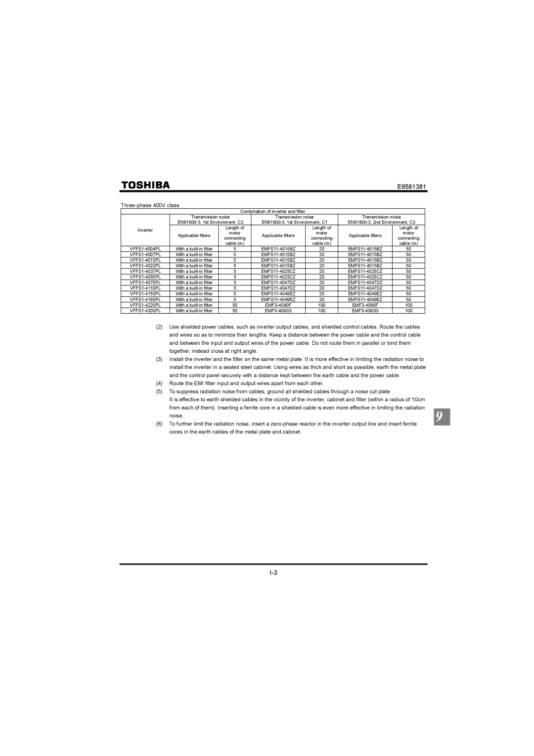
| Combination of inverter and filter |
|
|
|
|
|
| |||
|
| Transmission noise |
| Transmission noise | Transmission noise |
|
|
| ||||
|
|
|
|
|
| |||||||
| Inverter |
| Length of |
|
| Length of |
| Length of |
|
|
| |
| Applicable filters | motor |
| Applicable filters | motor | Applicable filters | motor |
|
|
| ||
|
|
|
|
|
| |||||||
|
| connecting |
| connecting | connecting |
|
|
| ||||
|
|
|
|
|
|
|
|
| ||||
|
|
| cable (m) |
|
| cable (m) |
| cable (m) |
|
|
| |
| With a | 5 |
| 20 | 50 |
|
|
| ||||
| With a | 5 |
| 20 | 50 |
|
|
| ||||
| With a | 5 |
| 20 | 50 |
|
|
| ||||
| With a | 5 |
| 20 | 50 |
|
|
| ||||
| With a | 5 |
| 20 | 50 |
|
|
| ||||
| With a | 5 |
| 20 | 50 |
|
|
| ||||
| With a | 5 |
| 20 | 50 |
|
|
| ||||
| With a | 5 |
| 20 | 50 |
|
|
| ||||
| With a | 5 |
| 20 | 50 |
|
|
| ||||
| With a | 5 |
| 20 | 50 |
|
|
| ||||
| With a | 50 |
| 100 | 100 |
|
|
| ||||
| With a | 50 |
| 100 | 100 |
|
|
| ||||
| (2) Use shielded power cables, such as inverter output cables, and shielded control cables. Route the cables |
|
| |||||||||
|
| and wires so as to minimize their lengths. Keep a distance between the power cable and the control cable |
|
| ||||||||
|
| and between the input and output wires of the power cable. Do not route them in parallel or bind them |
|
| ||||||||
|
| together, instead cross at right angle. |
|
|
|
|
|
|
| |||
| (3) Install the inverter and the filter on the same metal plate. It is more effective in limiting the radiation noise to |
|
| |||||||||
|
| install the inverter in a sealed steel cabinet. Using wires as thick and short as possible, earth the metal plate |
|
| ||||||||
|
| and the control panel securely with a distance kept between the earth cable and the power cable. |
|
| ||||||||
| (4) Route the EMI filter input and output wires apart from each other. |
|
|
|
|
| ||||||
| (5) To suppress radiation noise from cables, ground all shielded cables through a noise cut plate. |
|
|
|
| |||||||
|
| It is effective to earth shielded cables in the vicinity of the inverter, cabinet and filter (within a radius of 10cm |
|
| ||||||||
|
| from each of them). Inserting a ferrite core in a shielded cable is even more effective in limiting the radiation |
|
| ||||||||
|
|
| 9 | |||||||||
|
| noise. |
|
|
|
|
|
|
|
| ||
| (6) To further limit the radiation noise, insert a |
| ||||||||||
| ||||||||||||
cores in the earth cables of the metal plate and cabinet.