E6581381
2.3Description of terminals
2.3.1Power circuit terminals
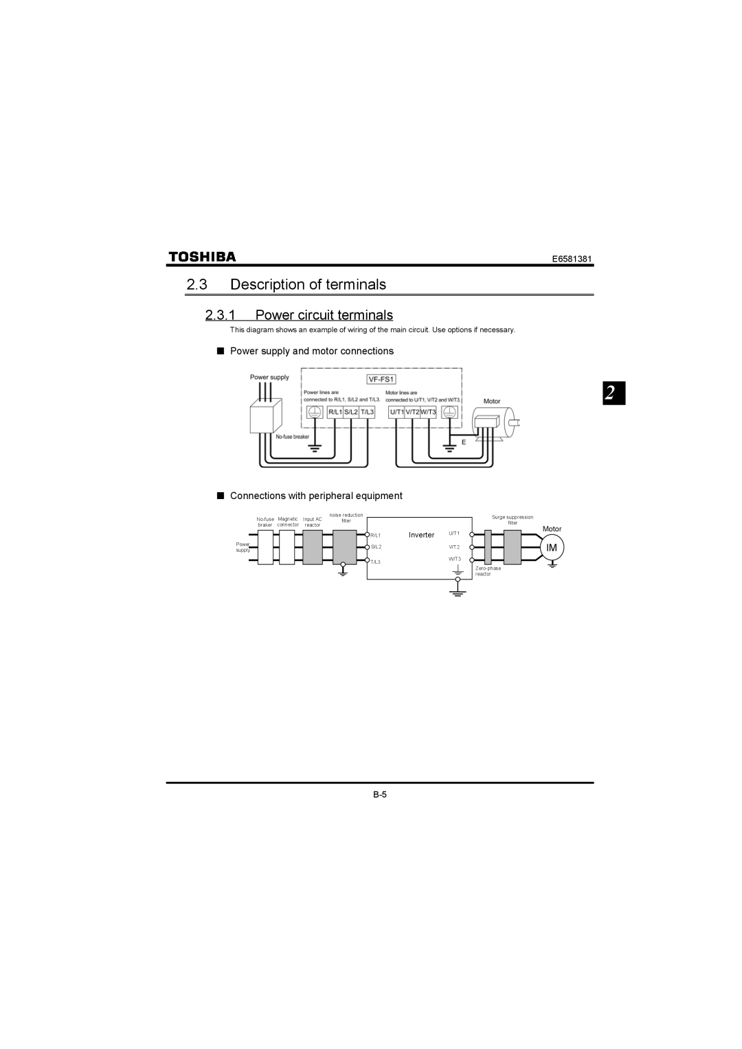
This diagram shows an example of wiring of the main circuit. Use options if necessary.
■Power supply and motor connections
2
■Connections with peripheral equipment
| Magnetic | Input AC | noise reduction |
|
| ||||||||
|
| filter |
|
|
| ||||||||
|
| braker | connector | reactor |
|
|
|
|
|
|
| ||
|
|
|
|
|
|
|
|
|
|
| R/L1 | Inverter | U/T1 |
|
|
|
|
|
|
|
|
|
|
|
| ||
Power |
|
|
|
|
|
|
|
|
| S/L2 |
| V/T2 | |
|
|
|
|
|
|
|
|
|
|
|
| ||
supply |
|
|
|
|
|
|
|
| |||||
|
|
|
|
|
|
|
|
|
|
|
| ||
|
|
|
|
|
|
|
|
|
|
| T/L3 |
| W/T3 |
|
|
|
|
|
|
|
|
|
|
|
|
|
|
|
|
|
|
|
|
|
|
|
|
|
|
|
|
Surge suppression
filter
Motor
IM