114RS SWEEPER specifications
The Nilfisk-ALTO 114RS Sweeper is a powerful and efficient machine designed to meet the demanding needs of commercial and industrial cleaning applications. This versatile equipment is widely recognized for its durability, ease of use, and advanced features, making it an essential tool for maintaining cleanliness in various environments such as warehouses, shopping centers, and outdoor spaces.One of the standout features of the Nilfisk-ALTO 114RS is its robust design. Constructed with high-quality materials, this sweeper is built to withstand tough working conditions while ensuring long-lasting performance. The ergonomic design makes it easy to maneuver, even in tight spaces, allowing operators to clean large areas quickly and effectively.
The Nilfisk-ALTO 114RS is equipped with a powerful suction system that delivers excellent dust control. This technology minimizes airborne particles, providing a cleaner and healthier environment for both workers and customers. The dual filter system enhances dust collection efficiency, extending the lifespan of the filters and reducing maintenance needs.
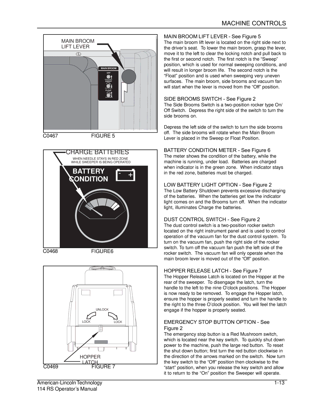
Another notable characteristic of the 114RS is its advanced intuitive controls. The user-friendly interface simplifies operation, enabling operators to focus on cleaning rather than navigating complex settings. The adjustable sweeping speed allows for optimized performance based on the nature of the task, ensuring thorough cleaning without compromising efficiency.
In addition, the Nilfisk-ALTO 114RS features a large debris hopper that can hold a significant amount of waste, reducing the frequency of emptying and allowing for continuous operation over extended periods. The easy-to-empty hopper further enhances productivity, making it convenient for workers to dispose of collected debris quickly.
The battery-powered version of the 114RS provides the added benefit of being environmentally friendly and quieter compared to gas-powered alternatives. This makes it suitable for use in noise-sensitive areas, such as hospitals or schools, without disrupting daily activities.
Overall, the Nilfisk-ALTO 114RS Sweeper combines powerful cleaning performance, advanced technology, and user-friendly design. Its robust construction, dust control capabilities, efficient operation, and environmental considerations make it an ideal choice for businesses seeking to maintain high cleanliness standards while maximizing operational efficiency. The 114RS is not just a sweeper; it is a reliable partner in achieving a cleaner and more productive workspace.

