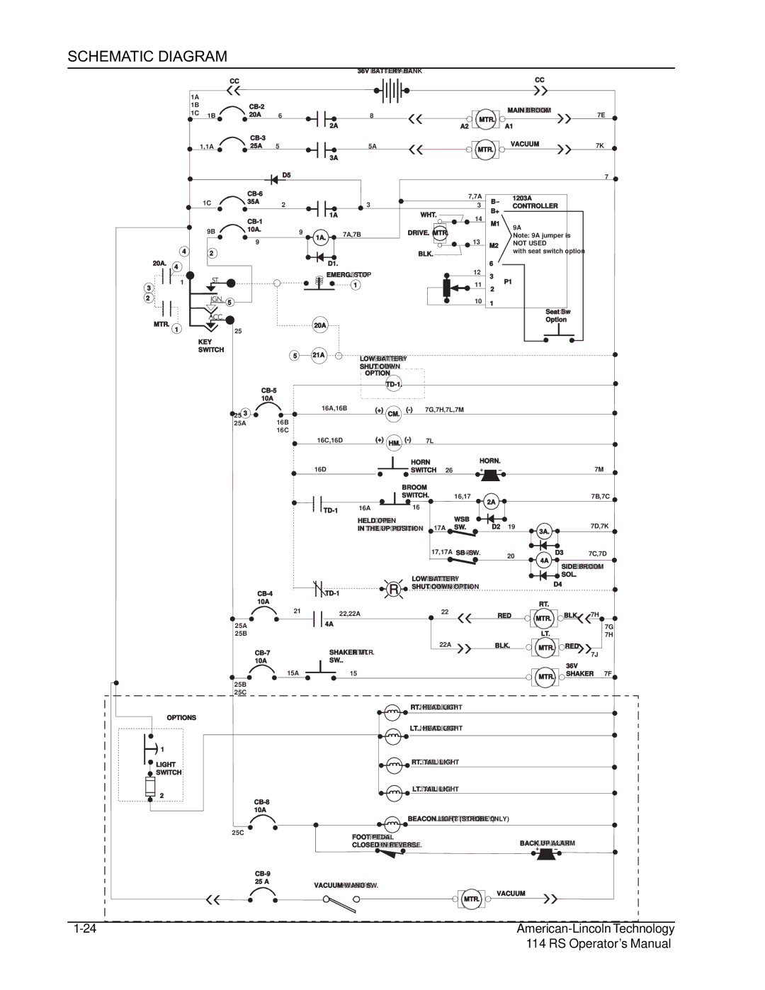
SCHEMATIC DIAGRAM

1A

1B

1C 1B

1,1A

1C

9B

4 2

20A. 4

1

3

2

MTR.

1

KEY

SWITCH


36V BATTERY BANK


CC


CC


CB-2


MAIN BROOM


20A


7E

6


8


MTR.


2A


A2


A1


CB-3


25A

5


5A


VACUUM

7K


MTR.


3A


D5


7


CB-6


7,7A


1203A


35A


B -


2


3


3

CONTROLLER


B+


1A

WHT.


14


CB-1


M1


9A


10A.


9


7A,7B

DRIVE. MTR.


1A.


Note: 9A jumper is


9


13


M2

NOT USED


BLK.


with seat switch option


D1.


6


EMERG. STOP


12

3


1


11


P1


2


5


10

1


Seat Sw


Option


20A


25


5


21A

LOW BATTERY


SHUT DOWN


OPTION


TD-1.


CB-5


10A


OPTIONS

1

LIGHT

SWITCH

2

25 3


16A,16B

(+)


(-)

7G,7H,7L,7M


CM.

25A

16B


16C


16C,16D

(+)

HM.

(-)

7L


HORN


16D


SWITCH

26


BROOM


SWITCH.


16,17


TD-1

16A


16


HELD OPEN


WSB


IN THE UP POSITION


17A

SW.


17,17A

SB -SW.


LOW BATTERY


SHUT DOWN OPTION


CB-4

TD-1


10A


21

22,22A


22


25A


4A


25B


22A


CB-7

SHAKER MTR.


10A

SW..


15A


15


25B

25C

RT. HEAD LIGHT

LT.. HEAD LIGHT

RT. TAIL LIGHT

LT. TAIL LIGHT

HORN.

7M

7B,7C

2A

D2

19

3A.


7D,7K


20


D3

7C,7D


4A


SIDE BROOM


SOL.


D4


RT.


RED

MTR.

BLK.

7H


7G


LT.


7H

BLK.


MTR.

RED


7J


36V


MTR.

SHAKER

7F


CB-8 10A


BEACON LIGHT (STROBE 0NLY)


25C

FOOT PEDAL


CLOSED IN REVERSE.

BACK UP ALARM


CB-9


25 A

VACUUM WAND SW.


VACUUM


MTR.


1-24

American-Lincoln Technology


114 RS Operator’s Manual

Page 25
Image 25
Nilfisk-ALTO 114RS SWEEPER manual Schematic Diagram, UP Position

114RS SWEEPER specifications

The Nilfisk-ALTO 114RS Sweeper is a powerful and efficient machine designed to meet the demanding needs of commercial and industrial cleaning applications. This versatile equipment is widely recognized for its durability, ease of use, and advanced features, making it an essential tool for maintaining cleanliness in various environments such as warehouses, shopping centers, and outdoor spaces.

One of the standout features of the Nilfisk-ALTO 114RS is its robust design. Constructed with high-quality materials, this sweeper is built to withstand tough working conditions while ensuring long-lasting performance. The ergonomic design makes it easy to maneuver, even in tight spaces, allowing operators to clean large areas quickly and effectively.

The Nilfisk-ALTO 114RS is equipped with a powerful suction system that delivers excellent dust control. This technology minimizes airborne particles, providing a cleaner and healthier environment for both workers and customers. The dual filter system enhances dust collection efficiency, extending the lifespan of the filters and reducing maintenance needs.

Another notable characteristic of the 114RS is its advanced intuitive controls. The user-friendly interface simplifies operation, enabling operators to focus on cleaning rather than navigating complex settings. The adjustable sweeping speed allows for optimized performance based on the nature of the task, ensuring thorough cleaning without compromising efficiency.

In addition, the Nilfisk-ALTO 114RS features a large debris hopper that can hold a significant amount of waste, reducing the frequency of emptying and allowing for continuous operation over extended periods. The easy-to-empty hopper further enhances productivity, making it convenient for workers to dispose of collected debris quickly.

The battery-powered version of the 114RS provides the added benefit of being environmentally friendly and quieter compared to gas-powered alternatives. This makes it suitable for use in noise-sensitive areas, such as hospitals or schools, without disrupting daily activities.

Overall, the Nilfisk-ALTO 114RS Sweeper combines powerful cleaning performance, advanced technology, and user-friendly design. Its robust construction, dust control capabilities, efficient operation, and environmental considerations make it an ideal choice for businesses seeking to maintain high cleanliness standards while maximizing operational efficiency. The 114RS is not just a sweeper; it is a reliable partner in achieving a cleaner and more productive workspace.