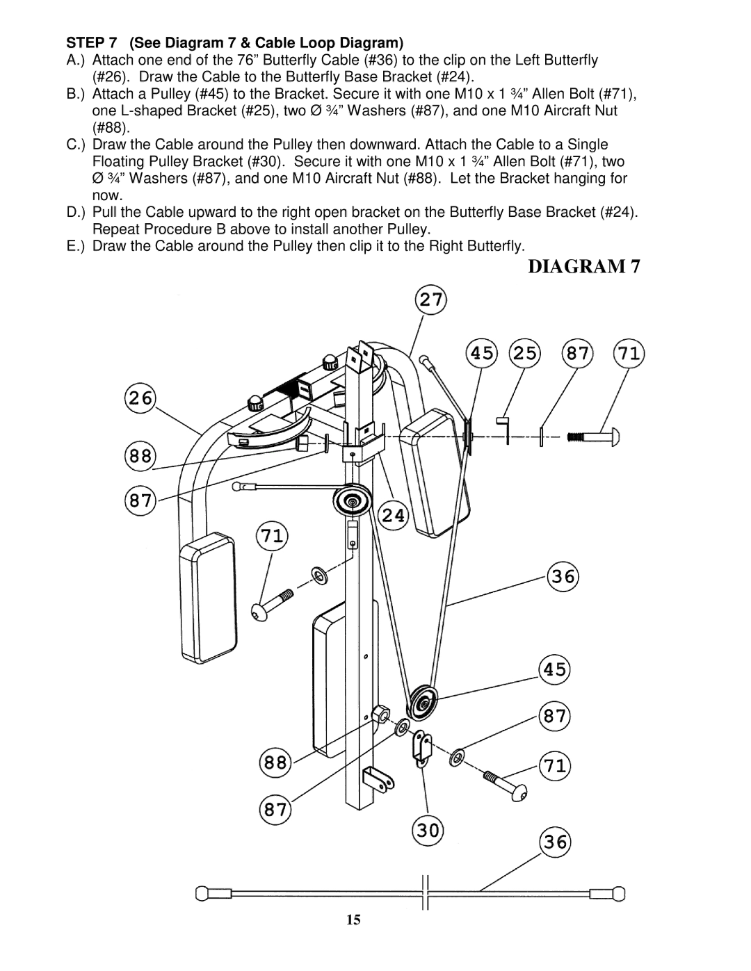
STEP 7 (See Diagram 7 & Cable Loop Diagram)
A.) Attach one end of the 76” Butterfly Cable (#36) to the clip on the Left Butterfly (#26). Draw the Cable to the Butterfly Base Bracket (#24).
B.) Attach a Pulley (#45) to the Bracket. Secure it with one M10 x 1 ¾” Allen Bolt (#71), one
C.) Draw the Cable around the Pulley then downward. Attach the Cable to a Single Floating Pulley Bracket (#30). Secure it with one M10 x 1 ¾” Allen Bolt (#71), two
ؾ” Washers (#87), and one M10 Aircraft Nut (#88). Let the Bracket hanging for now.
D.) Pull the Cable upward to the right open bracket on the Butterfly Base Bracket (#24). Repeat Procedure B above to install another Pulley.
E.) Draw the Cable around the Pulley then clip it to the Right Butterfly.
DIAGRAM 7
15