STEP 3 (See Diagram 3)
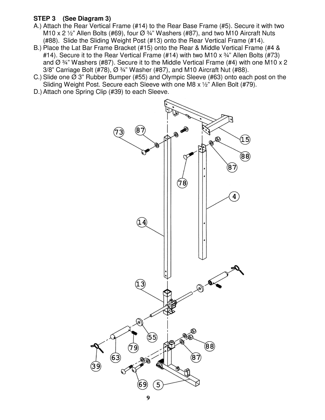
A.) Attach the Rear Vertical Frame (#14) to the Rear Base Frame (#5). Secure it with two M10 x 2 ½” Allen Bolts (#69), four Ø ¾” Washers (#87), and two M10 Aircraft Nuts (#88). Slide the Sliding Weight Post (#13) onto the Rear Vertical Frame (#14).
B.) Place the Lat Bar Frame Bracket (#15) onto the Rear & Middle Vertical Frame (#4 & #14). Secure it to the Rear Vertical Frame (#14) with two M10 x ¾” Allen Bolts (#73) and Ø ¾” Washers (#87). Secure it to the Middle Vertical Frame (#4) with one M10 x 2 3/8” Carriage Bolt (#78), Ø ¾” Washer (#87), and M10 Aircraft Nut (#88).
C.) Slide one Ø 3” Rubber Bumper (#55) and Olympic Sleeve (#63) onto each post on the Sliding Weight Post. Secure each Sleeve with one M8 x ½” Allen Bolt (#79).
D.) Attach one Spring Clip (#39) to each Sleeve.
9