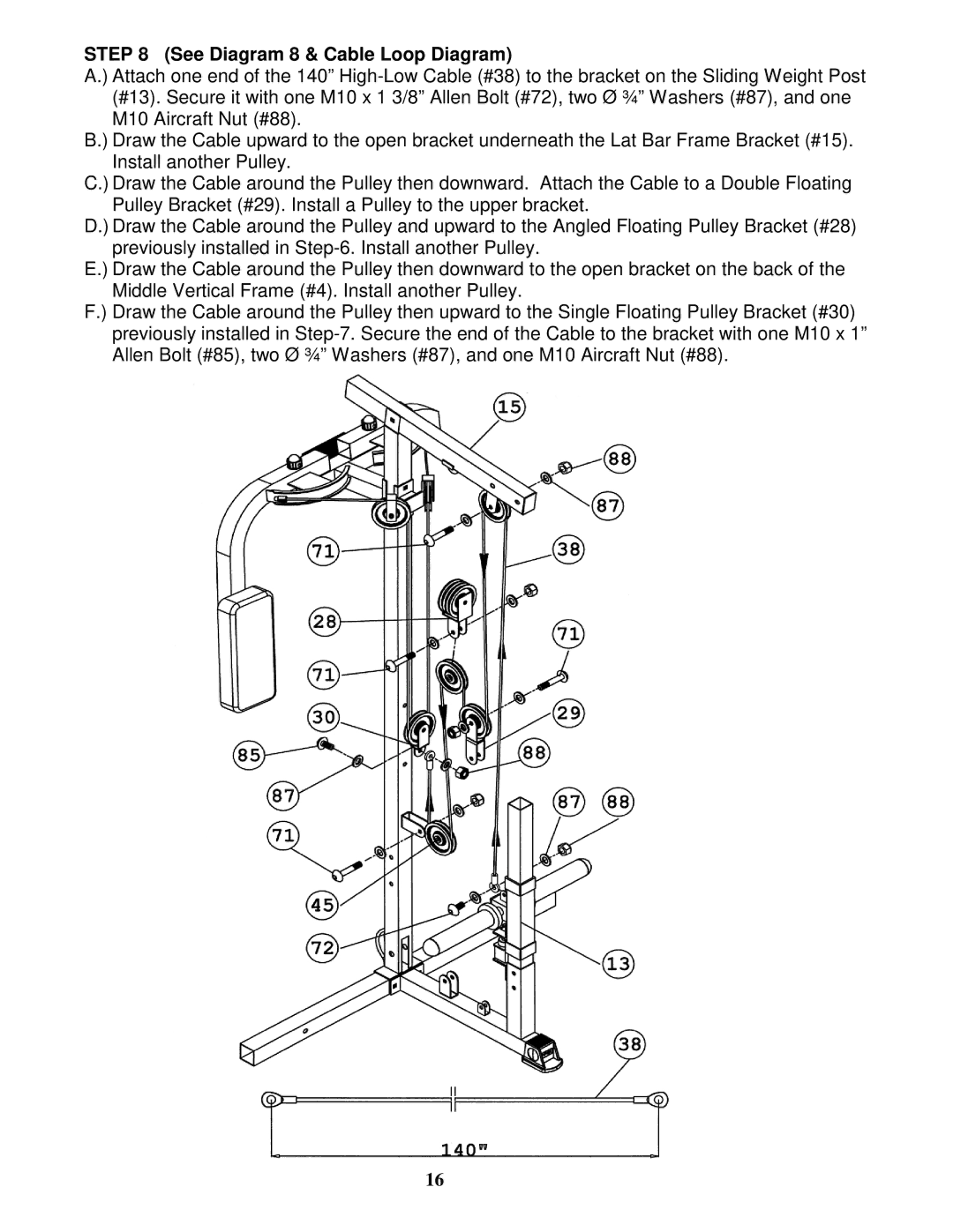
STEP 8 (See Diagram 8 & Cable Loop Diagram)
A.) Attach one end of the 140”
B.) Draw the Cable upward to the open bracket underneath the Lat Bar Frame Bracket (#15). Install another Pulley.
C.) Draw the Cable around the Pulley then downward. Attach the Cable to a Double Floating Pulley Bracket (#29). Install a Pulley to the upper bracket.
D.) Draw the Cable around the Pulley and upward to the Angled Floating Pulley Bracket (#28) previously installed in
E.) Draw the Cable around the Pulley then downward to the open bracket on the back of the Middle Vertical Frame (#4). Install another Pulley.
F.) Draw the Cable around the Pulley then upward to the Single Floating Pulley Bracket (#30) previously installed in
16