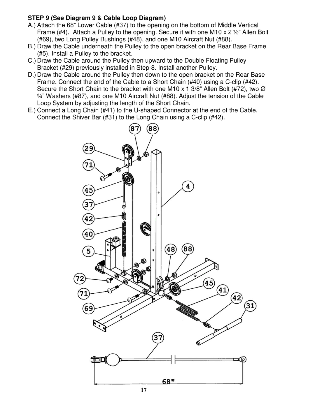
STEP 9 (See Diagram 9 & Cable Loop Diagram)
A.) Attach the 68” Lower Cable (#37) to the opening on the bottom of Middle Vertical Frame (#4). Attach a Pulley to the opening. Secure it with one M10 x 2 ½” Allen Bolt (#69), two Long Pulley Bushings (#48), and one M10 Aircraft Nut (#88).
B.) Draw the Cable underneath the Pulley to the open bracket on the Rear Base Frame (#5). Install a Pulley to the bracket.
C.) Draw the Cable around the Pulley then upward to the Double Floating Pulley Bracket (#29) previously installed in
D.) Draw the Cable around the Pulley then down to the open bracket on the Rear Base Frame. Connect the end of the Cable to a Short Chain (#40) using a
E.) Connect a Long Chain (#41) to the
17