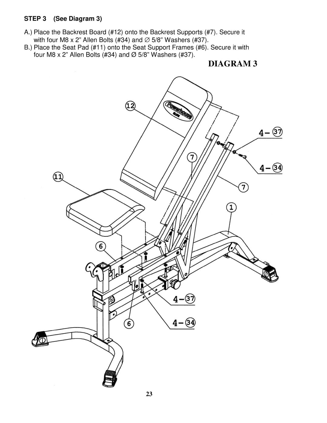
STEP 3 (See Diagram 3)
A.) Place the Backrest Board (#12) onto the Backrest Supports (#7). Secure it with four M8 x 2” Allen Bolts (#34) and ∅ 5/8” Washers (#37).
B.) Place the Seat Pad (#11) onto the Seat Support Frames (#6). Secure it with four M8 x 2” Allen Bolts (#34) and Ø 5/8” Washers (#37).
DIAGRAM 3
23