A
Appendices
is
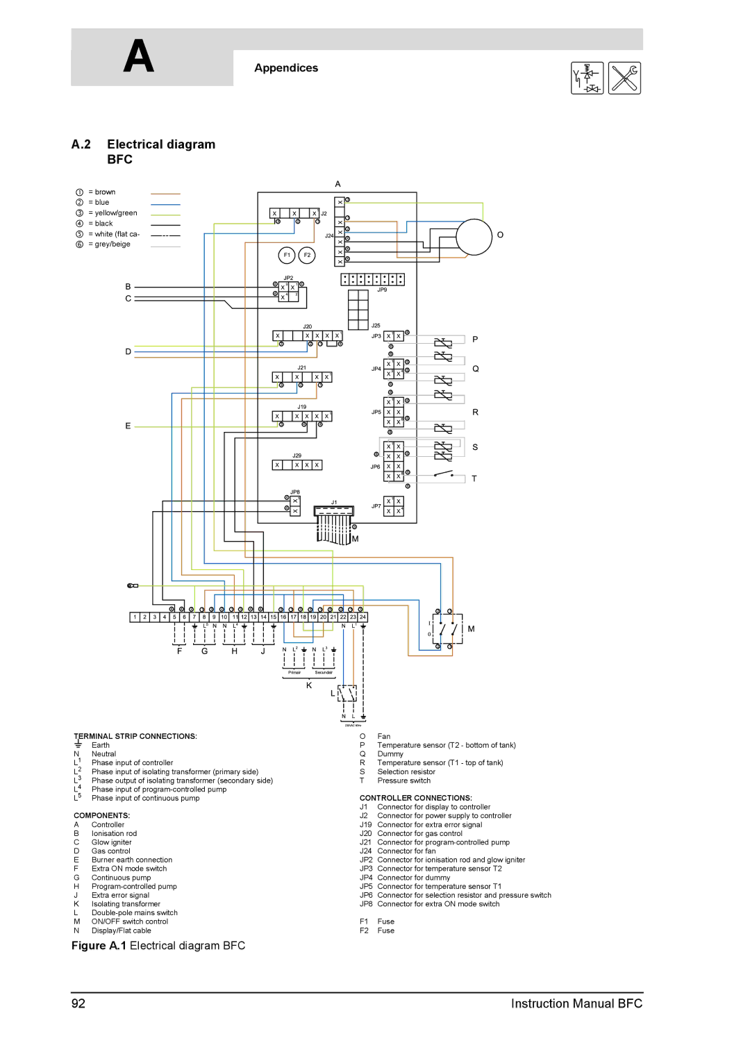
A.2 Electrical diagram
BFC
% = brown |
& = blue |
∋ = yellow/green |
( = black |
# = white (flat ca- |
∃ = grey/beige |
TERMINAL STRIP CONNECTIONS:
A Earth
NNeutral
L1 | Phase input of controller |
L2 | Phase input of isolating transformer (primary side) |
L3 | Phase output of isolating transformer (secondary side) |
L4 | Phase input of |
L5 | Phase input of continuous pump |
COMPONENTS:
AController
BIonisation rod C Glow igniter D Gas control
E Burner earth connection F Extra ON mode switch G Continuous pump
H
K Isolating transformer
L
OFan
PTemperature sensor (T2 - bottom of tank) Q Dummy
R Temperature sensor (T1 - top of tank) S Selection resistor
T Pressure switch
CONTROLLER CONNECTIONS:
J1 Connector for display to controller
J2 Connector for power supply to controller
J19 Connector for extra error signal
J20 Connector for gas control
J21 Connector for
J24 Connector for fan
JP2 Connector for ionisation rod and glow igniter JP3 Connector for temperature sensor T2
JP4 Connector for dummy
JP5 Connector for temperature sensor T1
JP6 Connector for selection resistor and pressure switch JP8 Connector for extra ON mode switch
F1 Fuse
F2 Fuse
Figure A.1 Electrical diagram BFC
92 | Instruction Manual BFC |