is
Electrical connection
1
2
1 | 1 |
|
324
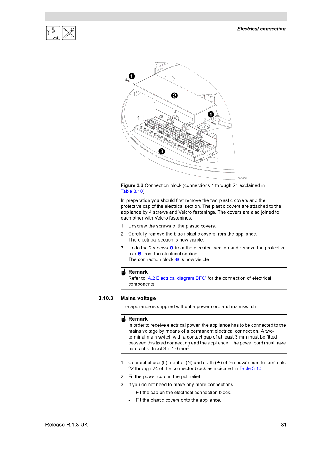
Figure 3.6 Connection block (connections 1 through 24 explained in Table 3.10)
In preparation you should first remove the two plastic covers and the protective cap of the electrical section. The plastic covers are attached to the appliance by 4 screws and Velcro fastenings. The covers are also joined to each other with Velcro fastenings.
1.Unscrew the screws of the plastic covers.
2.Carefully remove the black plastic covers from the appliance. The electrical section is now visible.
3.Undo the 2 screws 1 from the electrical section and remove the protective cap 2 from the electrical section.
The connection block 3 is now visible.
nRemark
Refer to ’A.2 Electrical diagram BFC’ for the connection of electrical components.
3.10.3Mains voltage
The appliance is supplied without a power cord and main switch.
nRemark
In order to receive electrical power, the appliance has to be connected to the mains voltage by means of a permanent electrical connection. A two- terminal main switch with a contact gap of at least 3 mm must be fitted between this fixed connection and the appliance. The power cord must have cores of at least 3 x 1.0 mm2.
1.Connect phase (L), neutral (N) and earth (A) of the power cord to terminals 22 through 24 of the connector block as indicated in Table 3.10.
2.Fit the power cord in the pull relief.
3.If you do not need to make any more connections:
-Fit the cap on the electrical connection block.
-Fit the plastic covers onto the appliance.
Release R.1.3 UK | 31 |