3
0 | I |
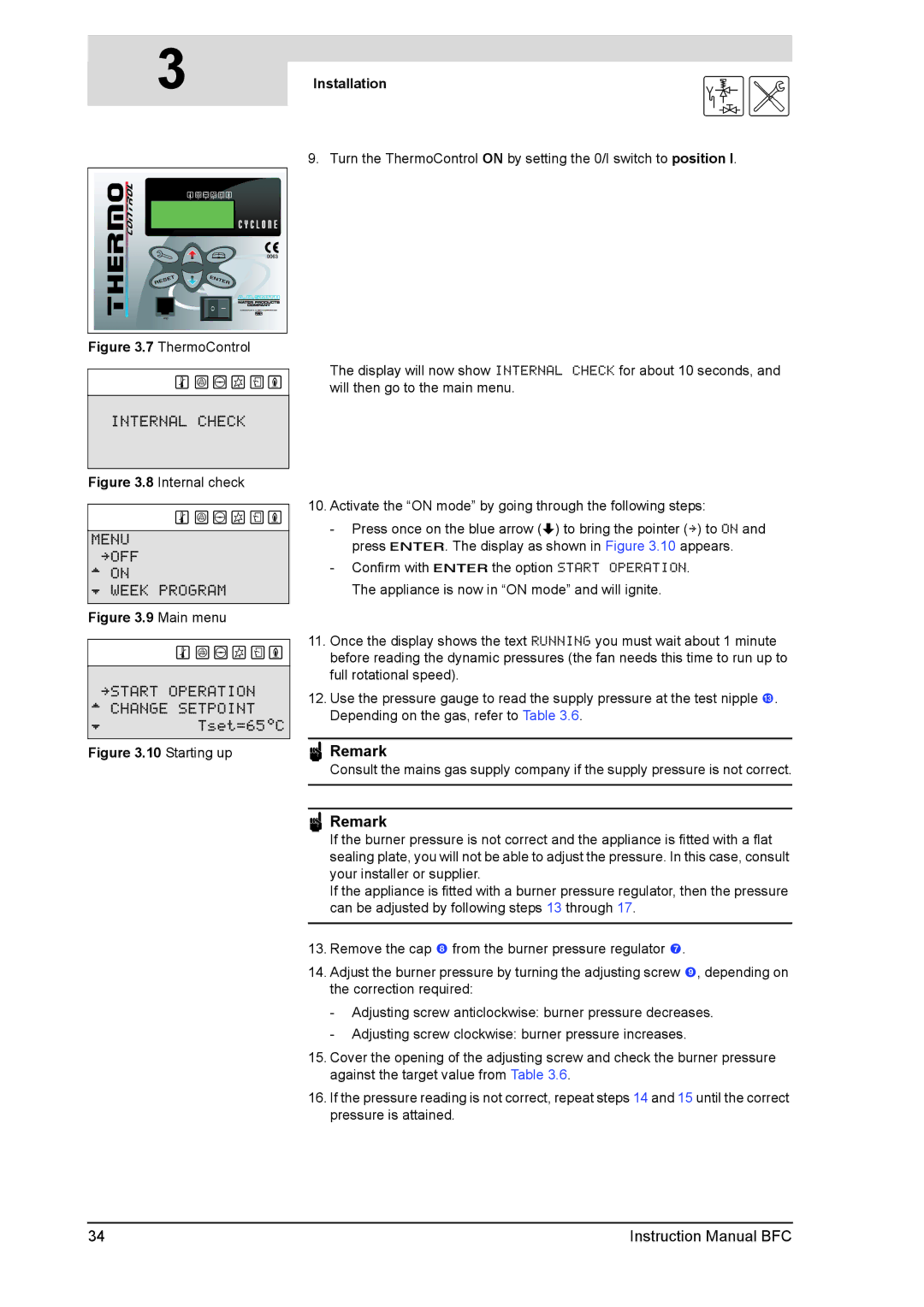
Figure 3.7 ThermoControl
INTERNAL CHECK
Figure 3.8 Internal check
MENU »OFF ^ ON
È WEEK PROGRAM
Figure 3.9 Main menu
»START OPERATION ^ CHANGE SETPOINT
ÈTset=65ÉC
Figure 3.10 Starting up
Installation | is |
|
9. Turn the ThermoControl ON by setting the 0/I switch to position I.
The display will now show INTERNAL CHECK for about 10 seconds, and will then go to the main menu.
10.Activate the “ON mode” by going through the following steps:
-Press once on the blue arrow (L) to bring the pointer (») to ON and press E. The display as shown in Figure 3.10 appears.
-Confirm with Ethe option START OPERATION. The appliance is now in “ON mode” and will ignite.
11.Once the display shows the text RUNNING you must wait about 1 minute before reading the dynamic pressures (the fan needs this time to run up to full rotational speed).
12.Use the pressure gauge to read the supply pressure at the test nipple #. Depending on the gas, refer to Table 3.6.
nRemark
Consult the mains gas supply company if the supply pressure is not correct.
nRemark
If the burner pressure is not correct and the appliance is fitted with a flat sealing plate, you will not be able to adjust the pressure. In this case, consult your installer or supplier.
If the appliance is fitted with a burner pressure regulator, then the pressure can be adjusted by following steps 13 through 17.
13.Remove the cap 8 from the burner pressure regulator 7.
14.Adjust the burner pressure by turning the adjusting screw 9, depending on the correction required:
-Adjusting screw anticlockwise: burner pressure decreases.
-Adjusting screw clockwise: burner pressure increases.
15.Cover the opening of the adjusting screw and check the burner pressure against the target value from Table 3.6.
16.If the pressure reading is not correct, repeat steps 14 and 15 until the correct pressure is attained.
34 | Instruction Manual BFC |
