gis
5
5.1Introduction
5.2Operating
^»START OPERATION È CHANGE SETPOINT
Tset=70ÉC
Figure 5.2 The display
Introduction
The control panel
Topics covered in this chapter:
•5.2 Operating;
•5.3 Explanation of the icons;
•5.4 ON/OFF switch of ThermoControl;
•5.5 Navigation buttons;
•5.6 PC connection..
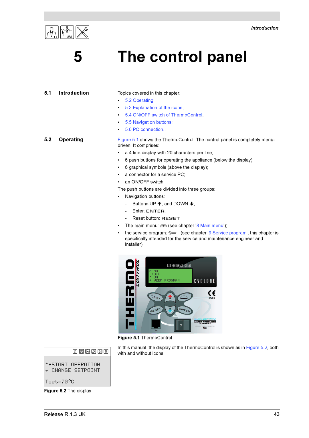
Figure 5.1 shows the ThermoControl. The control panel is completely menu- driven. It comprises:
•a 4-line display with 20 characters per line;
•6 push buttons for operating the appliance (below the display);
•6 graphical symbols (above the display);
•a connector for a service PC;
•an ON/OFF switch.
The push buttons are divided into three groups:
•Navigation buttons:
-Buttons UP H, and DOWN L;
-Enter: E;
-Reset button: R
•The main menu: B(see chapter ’8 Main menu’);
•the service program: S (see chapter ’9 Service program’, this chapter is specifically intended for the service and maintenance engineer and installer).
MENU »OFF ^ ON
» WEEK PROGRAM
0I
Figure 5.1 ThermoControl
In this manual, the display of the ThermoControl is shown as in Figure 5.2, both with and without icons.
Release R.1.3 UK | 43 |