3
3.10Electrical connection
Installation | is |
|
Warning
The installation should be carried out by an approved installer in compliance with the general and local regulations imposed by the gas, water and power supply companies and the fire service.
Refer also to paragraph ’1.3 Regulations’.
3.10.1Introduction
Topics covered in this paragraph:
•3.10.2 Preparation;
•3.10.3 Mains voltage;
Optionally, it is possible to connect an isolating transformer, a continuous pump, a
•3.10.4 Isolating Transformer;
•3.10.5 Continuous pump;
•3.10.6
•3.10.7 Extra ON mode switch (“Tank ON”);
•3.10.8 Connecting extra error signal (“Alarm OUT”).
nRemark
The optional components are not included in the rating for electrical power consumption (see tables in paragraph 3.4).
3.10.2Preparation
c Note
The appliance is
There should also be no potential difference present between neutral (N) and earth (A). If this is the case, then an isolating transformer must be applied in the supply circuit. See ’3.10.4 Isolating Transformer’.
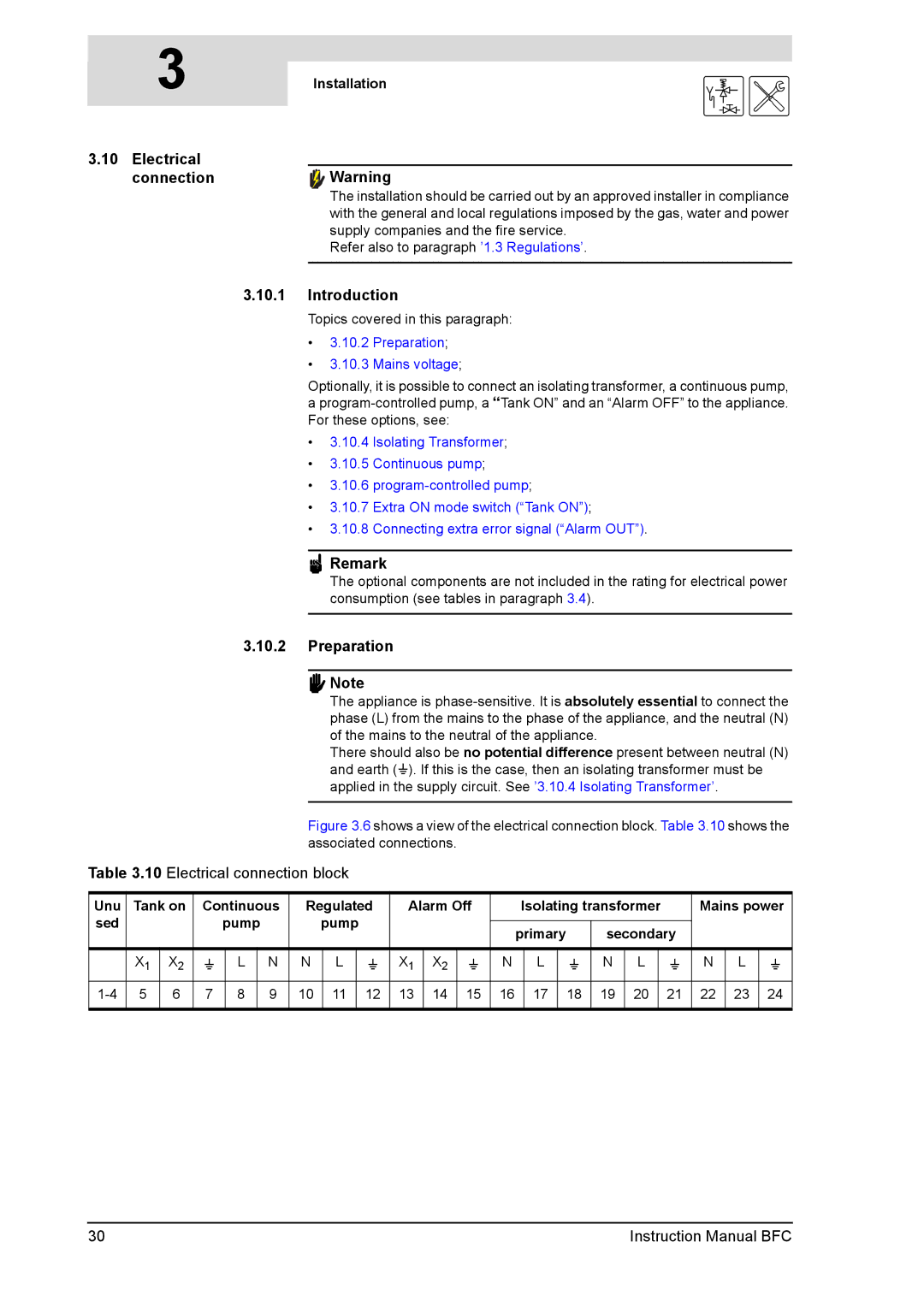
Figure 3.6 shows a view of the electrical connection block. Table 3.10 shows the associated connections.
Table 3.10 Electrical connection block
Unu | Tank on | Continuous | Regulated | Alarm Off | Isolating transformer | Mains power | |||||||||||||||
sed |
|
| pump | pump |
|
|
|
|
|
|
|
|
|
|
|
|
| ||||
|
|
|
|
| primary |
| secondary |
|
|
| |||||||||||
|
|
|
|
|
|
|
|
|
|
|
|
|
|
|
| ||||||
|
|
|
|
|
|
|
|
|
|
|
|
|
|
|
|
|
|
|
|
| |
| X1 | X2 | A | L | N | N | L | A | X1 | X2 | A | N | L | A | N | L | A | N | L | A | |
5 | 6 | 7 | 8 | 9 | 10 | 11 | 12 | 13 | 14 | 15 | 16 | 17 |
| 18 | 19 | 20 | 21 | 22 | 23 | 24 | |
|
|
|
|
|
|
|
|
|
|
|
|
|
|
|
|
|
|
|
|
|
|
30 | Instruction Manual BFC |
