8 TROUBLESHOOTING
8-2 No Error Indication
9 OPTIONAL SA-K97U RS-232C INTERFACE BOARD
Functions that can be controlled with front panel buttons and switches can also be controlled from a personal computer when the optional
Symptoms | Causes | Remedies |
|
No power is supplied. | q Is the power cord disconnected? | q Connect the power cord to an AC outlet. |
|
| q Is the [TIMER] indication shown? | q Press the [TIMER] button so that the |
|
| q Is the Operation Lock mode | [TIMER] indication goes out. |
|
| engaged? | q Release the Operation Lock mode. |
|
|
|
|
|
Operation buttons have no effect | Is the Operation Lock mode | Release the Operation Lock mode. |
|
during recording and playback. | engaged? |
| |
|
| ||
|
|
|
|
No picture is shown during | q Is the monitor connected correctly? | q Connect the monitor correctly. |
|
playback. | q Is the [TIMER] indication lit? | q Press the [TIMER] button to clear the |
|
|
| [TIMER] indication. |
|
|
|
|
|
Noise appears in the picture in | This is not a malfunction. |
|
|
the Shuttle Search mode, Still |
| — |
|
mode and Field Advance mode. |
|
|
|
Noise appears in part of the | Is the tracking adjusted properly? | Adjust the tracking with the [TRACKNG |
|
playback picture. |
|
| |
|
|
|
|
When the cassette is played | Dust may have accumulated on the | Clean the heads with a commercially- |
|
back, the picture becomes | video heads. | available head cleaning tape. If the picture |
|
rough or disappears. |
| quality is still unsatisfactory, consult your |
|
|
| local JVC dealer. |
|
|
|
|
|
No sound is heard during | q Are you recording in a timelapse | Use a tape on which sound is recorded. |
|
playback. | mode? If so, sound is not recorded. |
|
|
| q During alarm scan, no sound is |
|
|
| output. |
|
|
|
|
|
|
Recording is impossible. | Has the cassette safety tab been | Paste a piece of cellophane tape over |
|
| removed? | the hole. |
|
Timer recording is not working. | q Is the clock set correctly? Is the | q Check again. |
|
| timer properly programmed? |
|
|
| q Is the [TIMER] indication lit? | q Check it again. |
|
|
|
|
|
The clock cannot be set. | Is the [TIMER] indication lit? | Press the [TIMER] button so that the |
|
|
| [TIMER] indication goes out. |
|
|
|
|
|
Tape running sound is heard in | During recording and playback, the | If you feel it is too noisy, install the VCR |
|
the Record, Play, FF and REW | VCR’s motor and rotary heads are | in a rack. |
|
modes. | running. The sound this generates is |
|
|
| normal and not a malfunction. |
|
|
|
|
|
|
The time/date is not shown. | q Is the clock set? | q Set the clock. |
|
| q Is the <ON SCREEN MODE> | q Set the <ON SCREEN MODE> menu |
|
| menu switch set to “OFF”? | switch to “ON”. |
|
Auto REW and repeat recording | Is the <TAPE END MODE> menu | Set the <TAPE END MODE> menu |
|
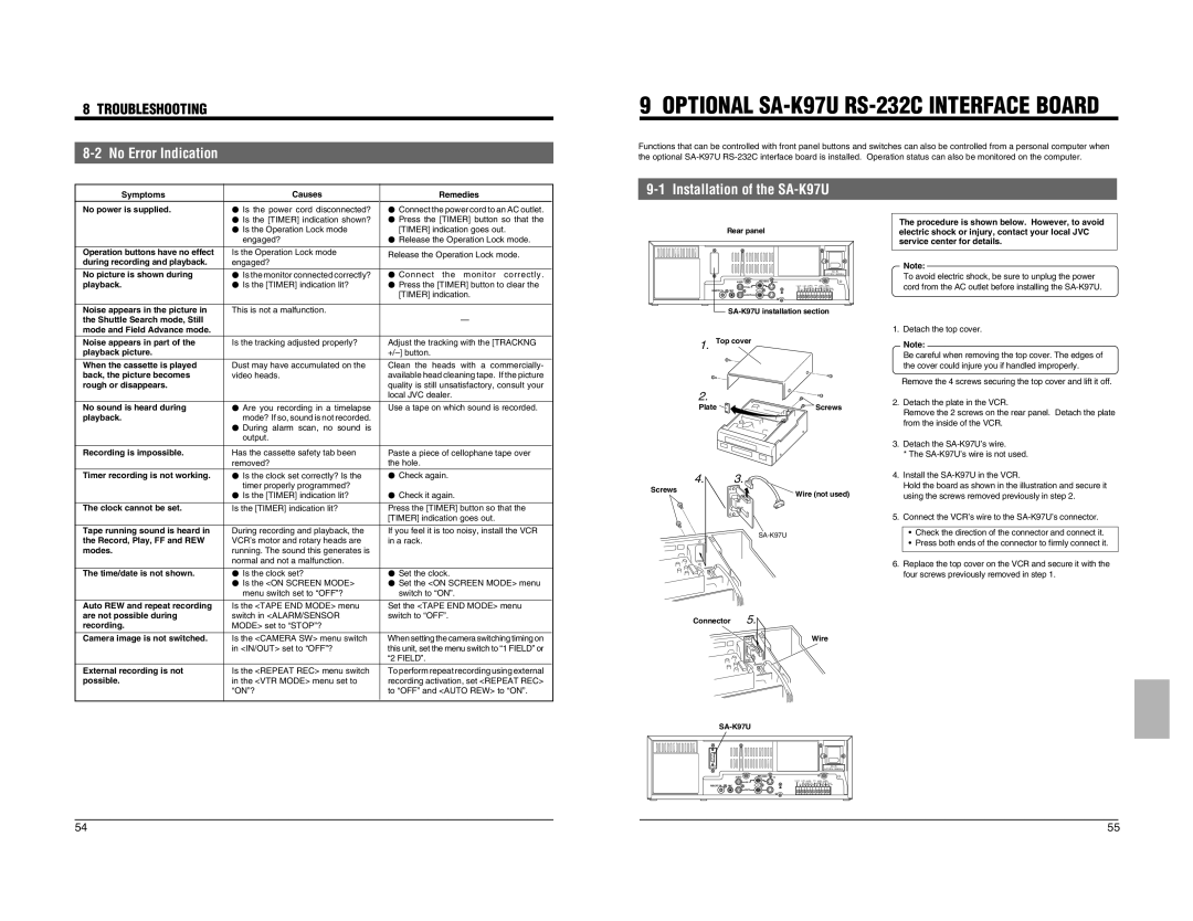
9-1 Installation of the SA-K97U
Rear panel
|
| AC~IN |
|
| AC120V~50/60Hz |
| AUDIO | VIDEO Y/C |
| IN |
|
REMOTE | MIC |
|
| OUT |
|
| ||
1. Top cover |
| |
2. |
|
|
Plate |
| Screws |
4. | 3. |
|
Screws |
| Wire (not used) |
|
| |
|
| |
The procedure is shown below. However, to avoid electric shock or injury, contact your local JVC service center for details.
Note:
To avoid electric shock, be sure to unplug the power cord from the AC outlet before installing the
1.Detach the top cover.
Note:
Be careful when removing the top cover. The edges of the cover could injure you if handled improperly.
Remove the 4 screws securing the top cover and lift it off.
2.Detach the plate in the VCR.
Remove the 2 screws on the rear panel. Detach the plate from the inside of the VCR.
3.Detach the
*The
4.Install the
Hold the board as shown in the illustration and secure it using the screws removed previously in step 2.
5.Connect the VCR’s wire to the
•Check the direction of the connector and connect it.
•Press both ends of the connector to firmly connect it.
6.Replace the top cover on the VCR and secure it with the four screws previously removed in step 1.
are not possible during | switch in <ALARM/SENSOR | switch to “OFF”. |
recording. | MODE> set to “STOP”? |
|
|
|
|
Camera image is not switched. | Is the <CAMERA SW> menu switch | When setting the camera switching timing on |
| in <IN/OUT> set to “OFF”? | this unit, set the menu switch to “1 FIELD” or |
|
| “2 FIELD”. |
External recording is not | Is the <REPEAT REC> menu switch | To perform repeat recording using external |
possible. | in the <VTR MODE> menu set to | recording activation, set <REPEAT REC> |
| “ON”? | to “OFF” and <AUTO REW> to “ON”. |
Connector 5.
Wire
AC~IN
AC120V~50/60Hz
AUDIO | VIDEO | Y/C |
IN
REMOTE ![]()
![]() MIC
MIC
OUT
54 | 55 |