3 CONNECTIONS
3-3 Connecting the Rear Panel Input/Output Terminal Connections
[CAM SW OUT] camera switching signal output terminal |
| [ALARM IN] alarm signal input terminal | ||||||||
CAM SW |
| ALARM | ||||||||
| IN COM | |||||||||
OUT COM |
| |||||||||
|
|
|
|
|
| |||||
|
|
|
|
|
|
|
|
|
|
|
|
|
| Sequential switcher |
|
|
|
|
| Sequential switcher |
|
|
|
| camera switching |
|
|
|
|
| alarm output |
|
|
|
|
|
|
|
|
| terminal |
| |
|
|
| signal input |
|
|
|
|
|
| |
|
|
|
|
|
|
|
|
|
| |
|
|
|
|
|
|
|
|
|
|
|
|
|
|
|
|
|
|
|
|
|
|
[ALARM RESET] alarm reset terminal |
| [ALARM REC OUT] alarm recording mode signal output terminal | ||||||||
|
|
|
|
|
|
|
|
|
|
|
4 ON-SCREEN/MENU SWITCHES
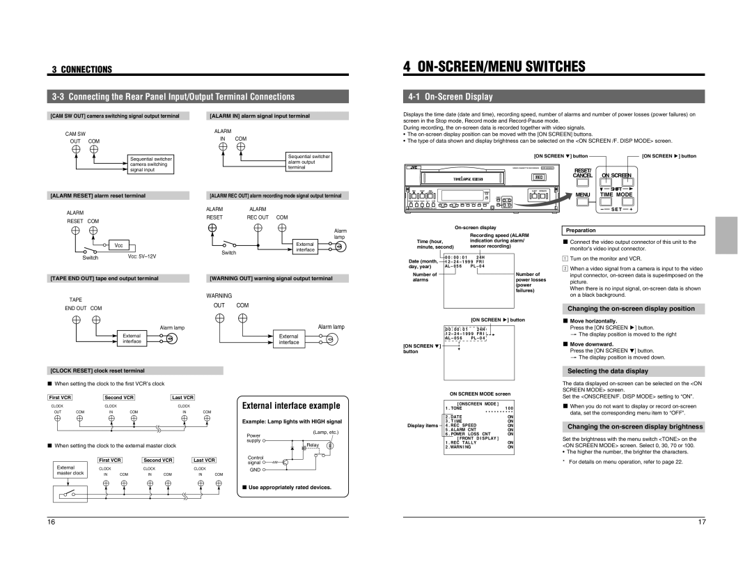
4-1 On-Screen Display
Displays the time date (date and time), recording speed, number of alarms and number of power losses (power failures) on screen in the Stop mode, Record mode and
During recording, the
•The
•The type of data shown and display brightness can be selected on the <ON SCREEN /F. DISP MODE> screen.
|
| [ON SCREEN 7] button | [ON SCREEN t] button | |
|
|
|
| |
|
| � | RESET/ |
|
|
|
| ON SCREEN | |
|
| REC | CANCEL | |
REC STOP REC |
| EJECT OPERATE |
| SHIFT |
CHECK | OPERATE |
| MENU | TIME MODE |
| HDR | RESET/ | ||
|
| CANCEL ON SCREEN |
|
|
REW REVERSE PAUSE PLAY FF |
| SHIFT |
|
|
TRACKING | V. LOCK TIMER SEARCH DISPLAY LOCK CNT RESET | MENU TIME MODE |
|
|
|
| –+ |
|
|
ALARM | ALARM | ALARM | |
RESET | REC OUT COM | ||
RESET COM | |||
|
| ||
| Vcc |
| |
| Switch |
| |
Switch | Vcc: |
|
Alarm lamp
External interface
FIELD REV |
| FIELD ADV – |
| + – |
|
| + |
|
| S E T | – |
| S E T |
| + | |||
|
|
|
|
|
|
|
|
| ||||||||||
|
|
|
|
|
|
|
|
|
|
|
| |||||||
|
|
|
|
|
|
| Preparation | |||||||||||
|
|
|
|
|
|
|
|
| Recording speed (ALARM | |||||||||
|
|
|
|
|
|
|
|
|
|
|
|
|
| |||||
|
|
|
|
|
|
|
|
|
|
|
|
|
| |||||
| Time (hour, |
|
|
|
| indication during alarm/ | 5 Connect the video output connector of this unit to the | |||||||||||
| minute, second) |
|
| sensor recording) | 1monitor’s video input connector. | |||||||||||||
|
|
|
|
| 0 0 : 0 0 | : 0 1 * * * 2 |
| 2Turn on the monitor and VCR. | ||||||||||
Date (month, |
|
| 4 H * * * * * * * * * * | |||||||||||||||
|
| |||||||||||||||||
|
| 1 2 – 2 4 | – 1 9 9 9 * FR I * * * * * * * * * * |
|
|
|
|
| ||||||||||
day, year) | AL – 0 | 5 | 6 * BL P L – 0 4 * AUTO * * * * * | When a video signal from a camera is input to the video | ||||||||||||||
* ZOOMONUM . * * * * * M. * * * * * * * | ||||||||||||||||||
|
|
|
|
| ||||||||||||||
Number of |
|
| * MACR * * T E L E | * * * * A . * * * * * * * | Number of | input connector, | ||||||||||||
[TAPE END OUT] tape end output terminal | [WARNING OUT] warning signal output terminal |
alarms | * DAT EEHEURE * * * * * * * * * * * * * | power losses | picture. |
| * DURE * * BANDE * * * T 4 5 * * * * * * | (power | |
| When there is no input signal, | ||
| * * * * * * * * * * * * * * * * * * * * * * * * | failures) | |
| * * * * * * * * * * * * * * * * * * * * * * * * |
|
WARNING
TAPE | OUT | COM | |
END OUT COM | |||
|
| ||
| Alarm lamp |
| |
| External |
| |
| interface |
|
Alarm lamp
External interface
| * * * * * * * * * * * * * * * * * * * * * * * * | on a black background. | |
| * * * * * * * * * * * * * * * * * * * * * * * * |
| |
| * 4F I N DE * MENU * * * * * * * * * * * | Changing the | |
|
|
| |
|
| [ON SCREEN t] button | 5 Move horizontally. |
| 0 0 : 0 0 : 0 1 * * * 2 4 H * * * * * * * * * * | Press the [ON SCREEN t] button. | |
| 1 2 – 2 4 – 1 9 9 9 * FR I * * * * * * * * * * | [ The display position is moved to the right | |
| AL – 0 5 6 * BL P L – 0 4 * AUTO * * * * * |
| |
| * ZOOMONUM . * * * * * M. * * * * * * * | 5 Move downward. | |
|
|
| |
[ON SCREEN 7] * MACR * * T E L E * * * * A . * * * * * * * | |||
button | * DAT EEHEURE * * * * * * * * * * * * * | Press the [ON SCREEN 7] button. | |
| * DURE * * BANDE * * * T 4 5 * * * * * * | [ The display position is moved down. | |
| * * * * * * * * * * * * * * * * * * * * * * * * | ||
| * * * * * * * * * * * * * * * * * * * * * * * * |
| |
| * * * * * * * * * * * * * * * * * * * * * * * * |
| |
[CLOCK RESET] clock reset terminal
* * * * * * * * * * * * * * * * * * * * * * * * | Selecting the data display |
* 4F I N DE * MENU * * * * * * * * * * * |
|
5When setting the clock to the first VCR’s clock
First VCR |
| Second VCR |
| Last VCR |
| External interface example | ||
CLOCK |
| CLOCK |
|
|
| CLOCK |
| |
OUT | COM | IN | COM |
|
| IN | COM |
|
|
|
|
|
|
|
|
| Example: Lamp lights with HIGH signal |
|
|
|
|
|
|
|
| (Lamp, etc.) |
|
|
|
|
|
|
|
| Power |
|
|
|
|
|
|
|
| supply |
5 When setting the clock to the external master clock |
|
| Relay | |||||
|
| First VCR | Second VCR | Last VCR | Control | |||
|
| signal | ||||||
External |
|
|
|
|
|
|
| |
| CLOCK |
| CLOCK |
| CLOCK | GND | ||
master clock | IN | COM |
|
|
|
| ||
IN | COM | IN |
| COM | ||||
5 Use appropriately rated devices.
Display items
ON SCREEN MODE screen
* * * * [ ONSCREEN * MODE ] * * * * *
1 | . TONEE * * * * * * * * * * * * * * 1 0 0 | |
* MANU . * BLANC * * * * * * * * * * * * | ||
|
|
|
2 | . DAT ENUM. * * * * * M. * * * * * ON | |
3. T I ME * T E L E * * * * A . * * * * * ON
4. REC * SPEED * * * * * * * * * * * ON
5. ALARMBCNT E * * * T 4 5 * * * * ON
6. POWERMLOSS * CNT I NE * * * ON * MOD [ FRONT * D I SP LAY ] * * * * *
1. REC * TAL L Y * * * * * * * * * * * ON
2 . WARN I NG * * * * * * * * * * * * * ON * 4 F I N * DE * MENU * * * * * * * * * * *
The data displayed
Set the <ONSCREEN/F. DISP MODE> setting to “ON”.
5When you do not want to display or record
Changing the on-screen display brightness
Set the brightness with the menu switch <TONE> on the <ON SCREEN MODE> screen. Select 0, 30, 70 or 100.
•The higher the number, the brighter the characters. * For details on menu operation, refer to page 22.
16 | 17 |