is
Installation diagram
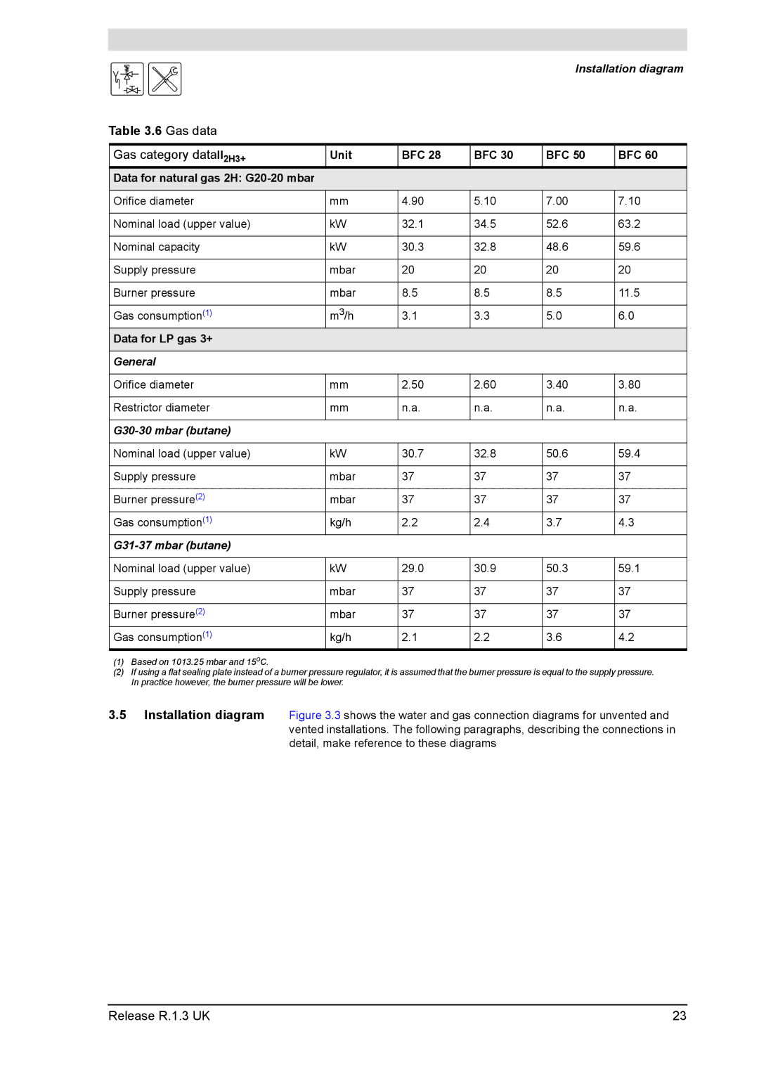
Table 3.6 Gas data
Gas category dataII2H3+ | Unit | BFC 28 | BFC 30 | BFC 50 | BFC 60 |
Data for natural gas 2H: |
|
|
|
|
|
Orifice diameter | mm | 4.90 | 5.10 | 7.00 | 7.10 |
|
|
|
|
|
|
Nominal load (upper value) | kW | 32.1 | 34.5 | 52.6 | 63.2 |
|
|
|
|
|
|
Nominal capacity | kW | 30.3 | 32.8 | 48.6 | 59.6 |
|
|
|
|
|
|
Supply pressure | mbar | 20 | 20 | 20 | 20 |
|
|
|
|
|
|
Burner pressure | mbar | 8.5 | 8.5 | 8.5 | 11.5 |
|
|
|
|
|
|
Gas consumption(1) | m3/h | 3.1 | 3.3 | 5.0 | 6.0 |
Data for LP gas 3+ |
|
|
|
|
|
|
|
|
|
|
|
General |
|
|
|
|
|
|
|
|
|
|
|
Orifice diameter | mm | 2.50 | 2.60 | 3.40 | 3.80 |
|
|
|
|
|
|
Restrictor diameter | mm | n.a. | n.a. | n.a. | n.a. |
|
|
|
|
|
|
|
|
|
|
|
|
|
|
|
|
|
|
Nominal load (upper value) | kW | 30.7 | 32.8 | 50.6 | 59.4 |
|
|
|
|
|
|
Supply pressure | mbar | 37 | 37 | 37 | 37 |
|
|
|
|
|
|
Burner pressure(2) | mbar | 37 | 37 | 37 | 37 |
Gas consumption(1) | kg/h | 2.2 | 2.4 | 3.7 | 4.3 |
|
|
|
|
|
|
|
|
|
|
|
|
Nominal load (upper value) | kW | 29.0 | 30.9 | 50.3 | 59.1 |
|
|
|
|
|
|
Supply pressure | mbar | 37 | 37 | 37 | 37 |
|
|
|
|
|
|
Burner pressure(2) | mbar | 37 | 37 | 37 | 37 |
Gas consumption(1) | kg/h | 2.1 | 2.2 | 3.6 | 4.2 |
(1)Based on 1013.25 mbar and 15oC.
(2)If using a flat sealing plate instead of a burner pressure regulator, it is assumed that the burner pressure is equal to the supply pressure. In practice however, the burner pressure will be lower.
3.5Installation diagram Figure 3.3 shows the water and gas connection diagrams for unvented and vented installations. The following paragraphs, describing the connections in detail, make reference to these diagrams
Release R.1.3 UK | 23 |
