4.11 MASTER SECTION
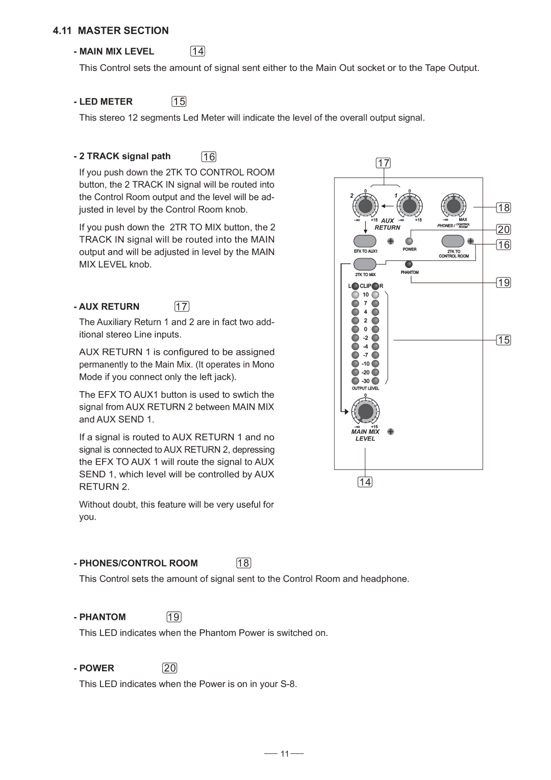
- MAIN MIX LEVEL | 14 |
This Control sets the amount of signal sent either to the Main Out socket or to the Tape Output.
- LED METER | 15 |
This stereo 12 segments Led Meter will indicate the level of the overall output signal.
- 2 TRACK signal path | 16 |
If you push down the 2TK TO CONTROL ROOM button, the 2 TRACK IN signal will be routed into the Control Room output and the level will be ad- justed in level by the Control Room knob.
If you push down the 2TR TO MIX button, the 2 TRACK IN signal will be routed into the MAIN output and will be adjusted in level by the MAIN MIX LEVEL knob.
- AUX RETURN | 17 |
The Auxiliary Return 1 and 2 are in fact two add- itional stereo Line inputs.
AUX RETURN 1 is configured to be assigned permanently to the Main Mix. (It operates in Mono Mode if you connect only the left jack).
The EFX TO AUX1 button is used to swtich the signal from AUX RETURN 2 between MAIN MIX and AUX SEND 1.
If a signal is routed to AUX RETURN 1 and no signal is connected to AUX RETURN 2, depressing the EFX TO AUX 1 will route the signal to AUX SEND 1, which level will be controlled by AUX RETURN 2.
Without doubt, this feature will be very useful for you.
| 17 |
|
|
|
|
|
| |
2 |
|
| 1 |
|
|
|
|
|
|
|
|
|
|
|
|
| 18 |
- 8 | +15 | AUX | - | 8 | +15 | - 8 | MAX |
|
|
|
|
|
|
| PHONES / | CONTROL |
|
| RETURN |
|
| ROOM | 20 | |||
|
|
|
|
| ||||
|
|
|
|
|
|
|
| |
EFX TO AUX1 |
|
| POWER | 2TK TO | 16 | |||
|
|
|
|
| ||||
|
|
|
|
|
| CONTROL ROOM |
| |
2TK TO MIX |
|
| PHANTOM |
|
|
| ||
|
|
|
|
|
|
| ||
L | CLIP | R |
|
|
|
|
| 19 |
| 10 |
|
|
|
|
|
|
|
| 7 |
|
|
|
|
|
|
|
| 4 |
|
|
|
|
|
|
|
| 2 |
|
|
|
|
|
|
|
| 0 |
|
|
|
|
|
|
|
|
|
|
|
|
|
| 15 | |
|
|
|
|
|
|
| ||
|
|
|
|
|
|
|
| |
|
|
|
|
|
|
|
| |
|
|
|
|
|
|
|
| |
|
|
|
|
|
|
|
| |
|
|
|
|
|
|
|
| |
OUTPUT LEVEL |
|
|
|
|
|
|
| |
- 8 | +15 |
|
|
|
|
|
|
|
MAIN MIX |
|
|
|
|
|
|
| |
LEVEL |
|
|
|
|
|
|
| |
14 |
|
|
|
|
|
|
| |
- PHONES/CONTROL ROOM | 18 |
This Control sets the amount of signal sent to the Control Room and headphone.
- PHANTOM 19
This LED indicates when the Phantom Power is switched on.
- POWER20
This LED indicates when the Power is on in your
11
