4. CONTROL ELEMENTS
4.1 The mono MIC/LINE channels | 1 |
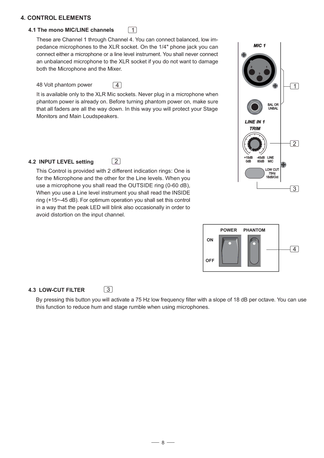
These are Channel 1 through Channel 4. You can connect balanced, low im- pedance microphones to the XLR socket. On the 1/4" phone jack you can connect either a microphone or a line level instrument. You shall never connect an unbalanced microphone to the XLR socket if you do not want to damage both the Microphone and the Mixer.
48 Volt phantom power | 4 |
It is available only to the XLR Mic sockets. Never plug in a microphone when phantom power is already on. Before turning phantom power on, make sure that all faders are all the way down. In this way you will protect your Stage Monitors and Main Loudspeakers.
4.2 INPUT LEVEL setting | 2 |
This Control is provided with 2 different indication rings: One is for the Microphone and the other for the Line levels. When you use a microphone you shall read the OUTSIDE ring
MIC 1
21
3
BAL OR
UNBAL
LINE IN 1
TRIM
+15dB
0dB 60dB MIC
LOW CUT
75Hz
18dB/Oct
1
2
3
POWER PHANTOM
ON
OFF
4.3 | 3 |
4
By pressing this button you will activate a 75 Hz low frequency filter with a slope of 18 dB per octave. You can use this function to reduce hum and stage rumble when using microphones.
8