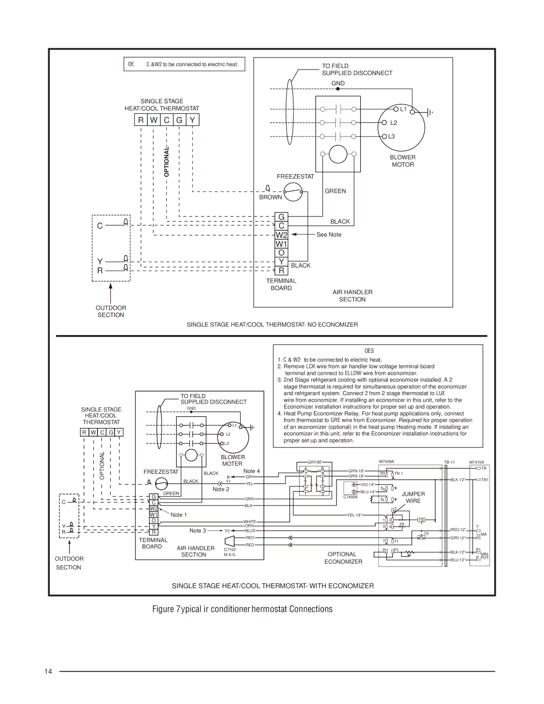
NOTE: C &W2 to be connected to electric heat.
SINGLE STAGE
HEAT/COOL THERMOSTAT
R W C G Y
OPTIONAL
C ![]()
Y ![]()
R ![]()
OUTDOOR
SECTION
| TO FIELD | |
| SUPPLIED DISCONNECT | |
| GND | |
| L1 | |
| L2 | |
| L3 | |
| BLOWER | |
| MOTOR | |
FREEZESTAT | ||
BROWN | GREEN | |
| ||
G | BLACK | |
C | ||
| ||
W2 | See Note | |
W1 |
| |
O |
| |
Y | BLACK | |
R |
| |
TERMINAL | ||
BOARD | ||
| AIR HANDLER | |
| SECTION | |
SINGLE STAGE HEAT/COOL THERMOSTAT- NO ECONOMIZER
SINGLE STAGE
HEAT/COOL
THERMOSTAT
R W C G Y
OPTIONAL
C ![]()
Y![]()
R![]()
OUTDOOR
SECTION
NOTES:
|
|
|
|
| 1. C & W2 to be connected to electric heat. |
|
|
|
| ||||
|
|
|
|
| 2. Remove BLACK wire from air handler low voltage terminal board |
| |||||||
|
|
|
|
| Y terminal and connect to YELLOW wire from economizer. |
|
| ||||||
|
|
|
|
| 3. 2nd Stage refrigerant cooling with optional economizer installed. A 2 |
| |||||||
|
|
|
|
| stage thermostat is required for simultaneous operation of the economizer |
| |||||||
|
| TO FIELD |
|
| and refrigerant system. Connect Y2 from 2 stage thermostat to BLUE |
| |||||||
|
|
|
| wire from economizer. If installing an economizer in this unit, refer to the |
| ||||||||
|
| SUPPLIED DISCONNECT |
| ||||||||||
|
| Economizer installation instructions for proper set up and operation. |
| ||||||||||
|
| GND |
|
|
| ||||||||
|
|
|
|
| 4. Heat Pump Economizer Relay. For heat pump applications only, connect B | ||||||||
|
|
| L1 |
| from thermostat to GREY wire from Economizer. Required for proper operation | ||||||||
|
|
|
| of an economizer (optional) in the heat pump Heating mode. If installing an |
| ||||||||
|
|
|
|
|
| ||||||||
|
|
| L2 |
| economizer in this unit, refer to the Economizer installation instructions for |
| |||||||
|
|
| L3 |
| proper set up and operation. |
|
|
|
|
|
| ||
|
|
|
|
|
|
|
|
|
|
|
|
| |
|
|
| BLOWER |
|
|
| W7459A | M7415A | |||||
|
|
| MOTER |
|
|
|
| ||||||
FREEZESTAT |
|
| Note 4 | A | B |
|
|
|
| TR | |||
BLACK |
| 7 | 9 | TR |
| TR 1 |
|
| |||||
B |
|
|
| ||||||||||
|
| BLACK | GRY |
|
|
|
|
| TR1 | ||||
|
| Y1 | YEL |
|
|
|
|
|
| ||||
|
| Note 2 | 4 | 6 |
| So |
|
|
|
| |||
| GREEN |
| s |
| JUMPER |
|
| ||||||
G |
|
|
| 1 | 3 |
|
|
|
| ||||
|
| GRN | C7400A |
| Sr |
|
|
| |||||
|
|
|
|
|
|
| WIRE |
|
| ||||
C |
|
|
|
|
|
|
|
|
|
| |||
|
|
| BLK |
|
|
|
|
|
|
|
|
| |
W2 |
|
|
|
|
|
|
|
|
| 5 |
|
| |
Note 1 |
|
|
|
|
|
|
|
|
|
| |||
W1 |
|
|
|
|
|
|
|
|
| ||||
O |
|
|
| WHITE |
|
|
|
| 1 | 2 | 1S |
|
|
Y |
|
|
| ORN |
|
|
|
| 3 | 4 | 2K |
| T |
| Note 3 |
|
|
|
|
|
| ||||||
R |
| Y2 | BLUE |
|
|
|
|
|
| 1S | T1MA | ||
|
|
|
|
|
|
|
|
|
|
| |||
TERMINAL |
|
| RED |
|
|
|
|
|
| ||||
|
| RED |
|
|
|
| T |
| T1 |
|
| ||
BOARD | AIR HANDLER |
|
|
|
|
|
|
|
|
|
| ||
C7150 |
|
|
|
|
| P |
| P1 |
| P1 | |||
|
|
|
| OPTIONAL |
|
| |||||||
|
| SECTION | M.A.S. |
|
|
|
|
|
|
| MIN. | ||
|
|
|
|
|
|
|
|
|
| ||||
|
|
|
|
|
|
| ECONOMIZER |
|
|
| P POT. | ||
|
|
|
|
|
|
|
|
|
|
|
| ||
SINGLE STAGE HEAT/COOL THERMOSTAT- WITH ECONOMIZER
Figure 7. Typical Air conditioner Thermostat Connections
14