ELECTRICAL WIRING
![]() WARNING:
WARNING:
To avoid risk of electrical shock, personal injury, or death, disconnect all electrical power to the unit before performing any maintenance or service. The unit may have more than one electrical supply.
Label all wires prior to disconnection when servicing the unit. Wiring errors can cause improper and dangerous operation.
•Electrical connections must be in compliance with all applicable local codes and ordinances, and with the current revision of the National Electric Code (ANSI/NFPA 70).
•For Canadian installations, the electrical connections and grounding shall comply with the current Canadian Electrical Code (CSA C22.1 and/or local codes).
Pre-Electrical Checklist:
√Verify that the voltage, frequency, and phase of the supply source match the specifications on the unit rating plate. The label is located near the refrigerant lines.
√Verify that the service provided by the utility is suffi cient to handle the additional load imposed by this equipment.
√Phase balance on 3 phase units must always be checked. See Unbalanced
Line Voltage
•It is recommended that the line voltage to the unit be supplied from a dedicated branch circuit containing the correct fuse or circuit breaker for the unit.
•An electrical disconnect must be located within sight of and readily accessible to the unit.This switch shall be capable of electrically
•Refer to the unit wiring label for proper high and low voltage wiring.
•Use only copper wire for the line voltage power supply to this unit (Table 2, page 6). Use proper code agency listed conduit and a conduit connector for connecting the supply wires to the unit.
•Overcurrent protection must be provided at the branch circuit distribution panel and sized as shown on the unit rating label and according to applicable local codes. See the unit rating plate for maximum circuit ampacity and maximum overcurrent protection limits.
•If replacing any of the original wires supplied with the unit, the replacement wire must be copper wire consisting of the same gauge and temperature rating.
•Provide power supply for the unit in accordance with the unit wiring diagram, and the unit rating plate. The installer should become familiar with the wiring diagram/
schematic before making any electrical connections to the unit. See Figure 6 (page 13).
•These air handlers can be purchased in both single and three phase power confi gurations, all single phase equipment is shipped from the factory ready for fi eld connections. For electrical connection locations see Figures 4 or 5 (pages 10 or 11).
•Three phase units are shipped from the factory pre- confi gured for high voltage operation. The 460 volt, 60 hertz units may be reconfi gured in the fi eld for the other voltages indicated on the unit rating label .For additional Maximum Current Ampacity (MCA), or Maximum Over- current Protection (MOP) information, refer to the unit rating label.For proper high voltage wiring or other wiring requirements refer to the Wiring Diagram (Figure 6).
•Internally mounted circuit breakers are available as field installed options. These circuit breakers can be used as an electrical disconnect.
Thermostat Connections
•Thermostat connections shall be in accordance with the instructions supplied with the thermostat and the indoor equipment. The low voltage wires must be properly connected to the units low voltage terminal block.
•A single stage thermostat is used with this equipment and must operate in conjunction with any installed accessories. A typical AC and air handler hookup is shown in Figure 7 (page 14). For heat pump and air handler connections, see Figure 8 (page 15).
•The thermostat should be mounted about 5 feet above the fl oor on an inside wall.DO NOT install the thermostat on an outside wall or any other location where its operation may be adversely affected by radiant heat from fi replaces, sunlight, or lighting fi xtures, and convective heat from warm air registers or electrical appliances. Refer to the thermostat manufacturer’s instruction sheet for detailed mounting and installation information.
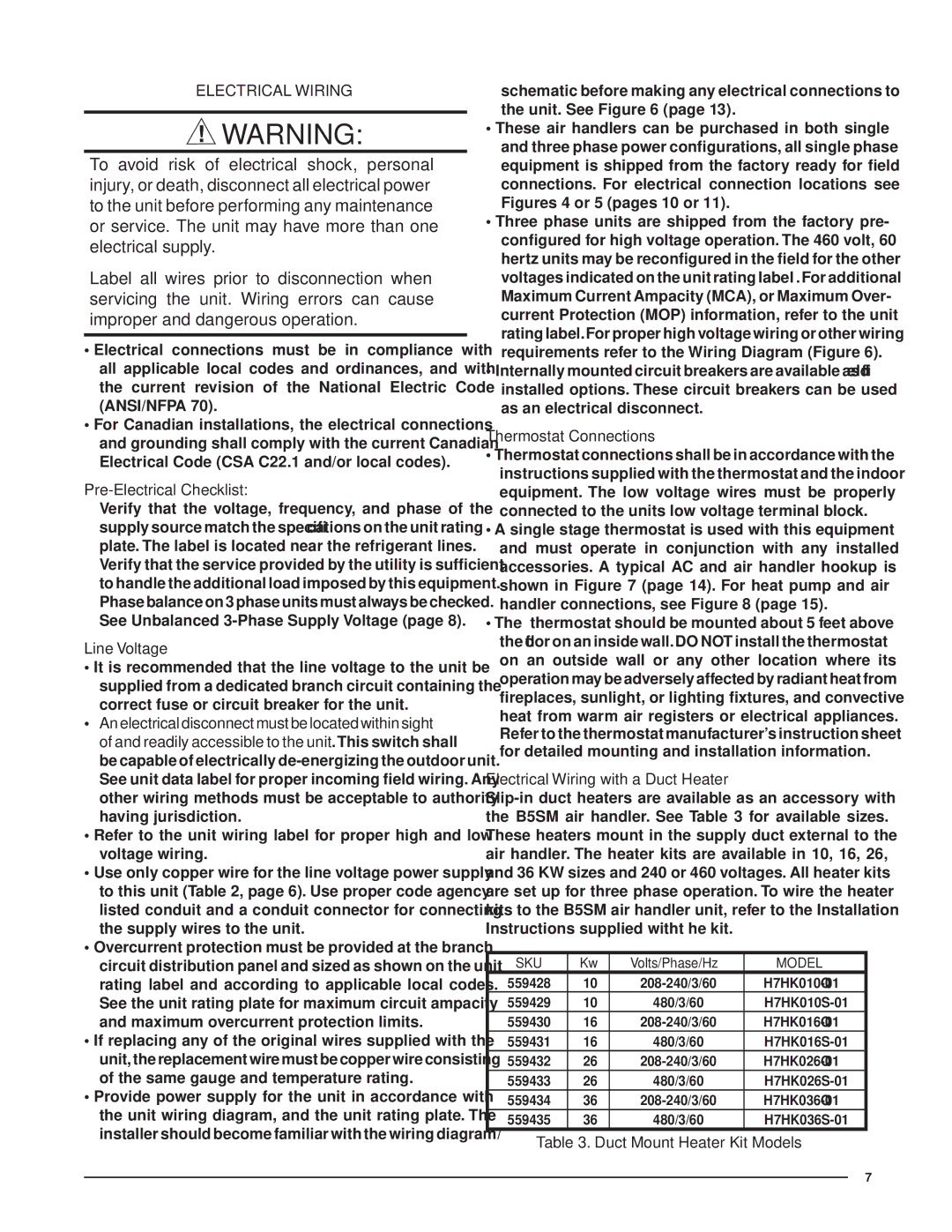
Electrical Wiring with a Duct Heater
SKU | Kw | Volts/Phase/Hz | MODEL |
559428 | 10 | ||
559429 | 10 | 480/3/60 | |
559430 | 16 | ||
559431 | 16 | 480/3/60 | |
559432 | 26 | ||
559433 | 26 | 480/3/60 | |
559434 | 36 | ||
559435 | 36 | 480/3/60 |
Table 3. Duct Mount Heater Kit Models
7