•The
•The
•Before brazing the
•Optional equipment such as liquid line solenoid valves, low ambient, etc., should be installed in strict accordance with the manufacturer’s installation instructions.
Filter Requirements
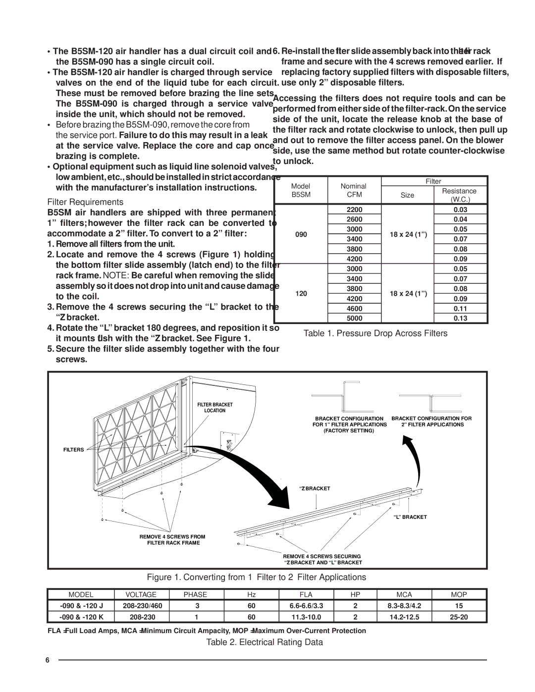
B5SM air handlers are shipped with three permanent 1” fi lters; however the fi lter rack can be converted to accommodate a 2” fi lter. To convert to a 2” fi lter:
1.Remove all filters from the unit.
2.Locate and remove the 4 screws (Figure 1) holding the bottom fi lter slide assembly (latch end) to the fi lter rack frame. NOTE: Be careful when removing the slide assembly so it does not drop into unit and cause damage to the coil.
3.Remove the 4 screws securing the “L” bracket to the “Z” bracket.
4.Rotate the “L” bracket 180 degrees, and reposition it so it mounts fl ush with the “Z” bracket. See Figure 1.
5.Secure the fi lter slide assembly together with the four screws.
6.
Accessing the fi lters does not require tools and can be performed from either side of the fi
Model | Nominal |
| Filter | |
|
| Resistance | ||
B5SM | CFM | Size |
| |
| (W.C.) | |||
|
|
|
| |
| 2200 |
|
| 0.03 |
| 2600 |
|
| 0.04 |
090 | 3000 | 18 x 24 (1”) |
| 0.05 |
3400 |
| 0.07 | ||
|
|
| ||
| 3800 |
|
| 0.08 |
| 4200 |
|
| 0.09 |
| 3000 |
|
| 0.05 |
| 3400 |
|
| 0.07 |
120 | 3800 | 18 x 24 (1”) |
| 0.08 |
4200 |
| 0.09 | ||
|
|
| ||
| 4600 |
|
| 0.11 |
| 5000 |
|
| 0.13 |
Table 1. Pressure Drop Across Filters
FILTER BRACKET |
|
LOCATION |
|
BRACKET CONFIGURATION | BRACKET CONFIGURATION FOR |
FOR 1” FILTER APPLICATIONS | 2” FILTER APPLICATIONS |
(FACTORY SETTING) |
|
FILTERS |
|
“Z” BRACKET |
|
| “L” BRACKET |
REMOVE 4 SCREWS FROM |
|
FILTER RACK FRAME |
|
REMOVE 4 SCREWS SECURING |
|
“Z” BRACKET AND “L” BRACKET |
|
Figure 1. Converting from 1” Filter to 2” Filter Applications
MODEL | VOLTAGE | PHASE | Hz | FLA | HP | MCA | MOP |
3 | 60 | 2 | 15 | ||||
|
|
|
|
|
|
|
|
1 | 60 | 2 |
FLA = Full Load Amps, MCA = Minimum Circuit Ampacity, MOP = Maximum
Table 2. Electrical Rating Data
6