12 Chapter 3 BST Doorphone Installation
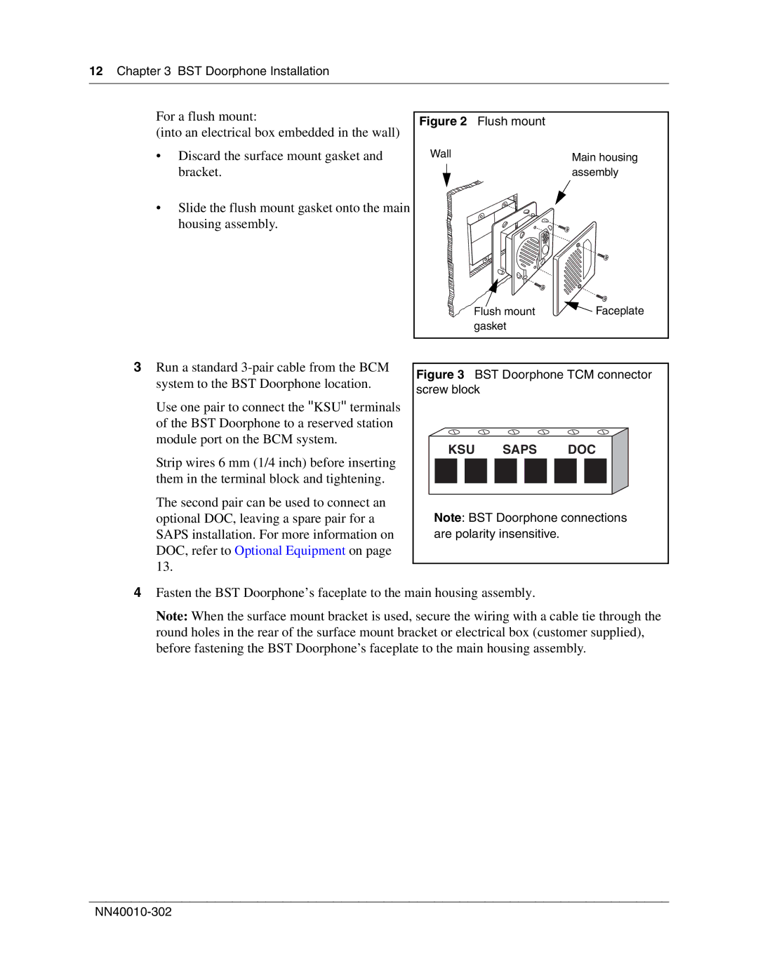
For a flush mount:
(into an electrical box embedded in the wall)
•Discard the surface mount gasket and bracket.
•Slide the flush mount gasket onto the main housing assembly.
Figure 2 Flush mount
Wall | Main housing |
| |
| assembly |
Flush mount | Faceplate |
gasket |
|
3Run a standard
Use one pair to connect the ''KSU'' terminals of the BST Doorphone to a reserved station module port on the BCM system.
Strip wires 6 mm (1/4 inch) before inserting them in the terminal block and tightening.
The second pair can be used to connect an optional DOC, leaving a spare pair for a SAPS installation. For more information on DOC, refer to Optional Equipment on page 13.
Figure 3 BST Doorphone TCM connector screw block
KSU SAPS DOC
Note: BST Doorphone connections are polarity insensitive.
4Fasten the BST Doorphone’s faceplate to the main housing assembly.
Note: When the surface mount bracket is used, secure the wiring with a cable tie through the round holes in the rear of the surface mount bracket or electrical box (customer supplied), before fastening the BST Doorphone’s faceplate to the main housing assembly.
