INSTALLATION IN NEW CONSTRUCTION (continued) |
| |||
WALL INLET INSTALLATION |
|
|
| |
MODEL 360 WALL INLET (361 |
|
|
| |
1. Remove the cardboard plaster guard. |
|
|
| |
2. Refer to Figure 17. For some drywall or panel construction, the |
|
|
| |
plaster frame will extend beyond the finished wall. In this case, |
|
|
| |
remove plaster frame from mounting bracket by removing |
|
|
| |
mounting screws. |
|
|
| |
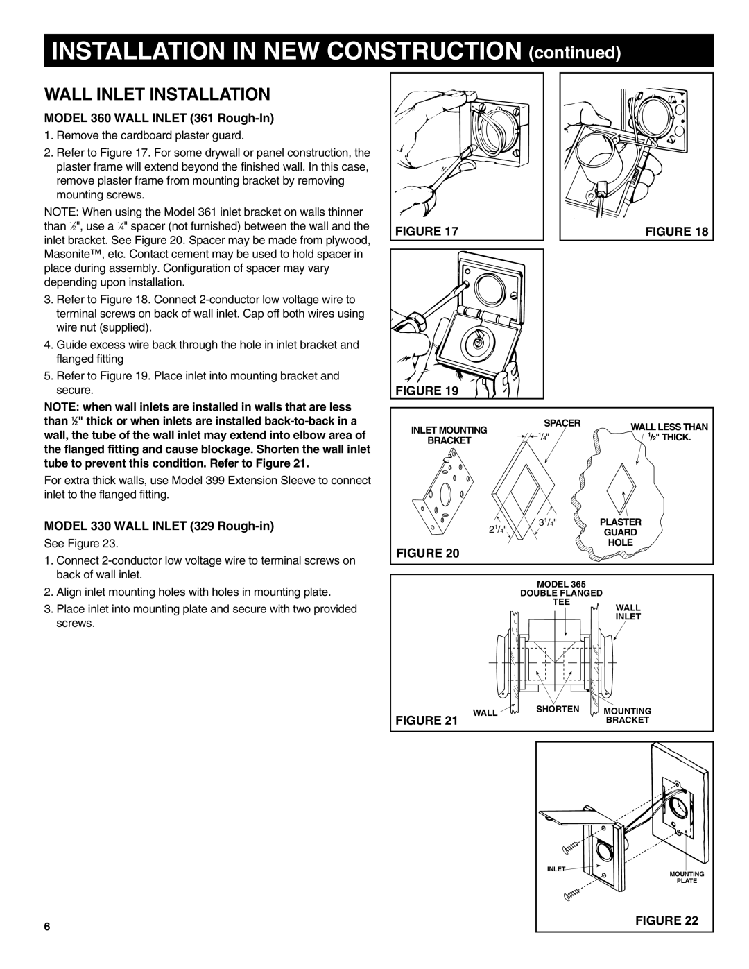
NOTE: When using the Model 361 inlet bracket on walls thinner |
|
|
| |
than 1⁄2", use a 1⁄4" spacer (not furnished) between the wall and the | FIGURE 17 |
| FIGURE 18 | |
inlet bracket. See Figure 20. Spacer may be made from plywood, |
| |||
|
|
| ||
Masonite™, etc. Contact cement may be used to hold spacer in |
|
|
| |
place during assembly. Configuration of spacer may vary |
|
|
| |
depending upon installation. |
|
|
| |
3. Refer to Figure 18. Connect |
|
|
| |
terminal screws on back of wall inlet. Cap off both wires using |
|
|
| |
wire nut (supplied). |
|
|
| |
4. Guide excess wire back through the hole in inlet bracket and |
|
|
| |
flanged fitting |
|
|
| |
5. Refer to Figure 19. Place inlet into mounting bracket and |
|
|
| |
secure. | FIGURE 19 |
|
| |
NOTE: when wall inlets are installed in walls that are less |
|
|
| |
than 1⁄2" thick or when inlets are installed | INLET MOUNTING | SPACER | WALL LESS THAN | |
wall, the tube of the wall inlet may extend into elbow area of |
| |||
1/4" | 1/2" THICK. | |||
BRACKET | ||||
the flanged fitting and cause blockage. Shorten the wall inlet |
|
| ||
|
|
| ||
tube to prevent this condition. Refer to Figure 21. |
|
|
| |
For extra thick walls, use Model 399 Extension Sleeve to connect inlet to the flanged fitting.
MODEL 330 WALL INLET (329 | 2 | 1 | /4" | 31/4" | PLASTER | |
See Figure 23. |
|
| GUARD | |||
FIGURE 20 |
|
|
| HOLE | ||
1. | Connect |
|
|
|
| |
|
|
|
|
| ||
| back of wall inlet. |
|
|
| MODEL 365 |
|
2. | Align inlet mounting holes with holes in mounting plate. |
|
|
|
| |
|
|
| DOUBLE FLANGED | |||
3. | Place inlet into mounting plate and secure with two provided |
|
|
| TEE | WALL |
|
|
|
| |||
| screws. |
|
|
|
| INLET |
|
|
|
|
|
| |
WALL | SHORTEN | MOUNTING |
FIGURE 21 |
| BRACKET |
| INLET | MOUNTING |
|
| |
|
| PLATE |
6 |
| FIGURE 22 |
|
|