INSTALLATION IN NEW CONSTRUCTION (continued)
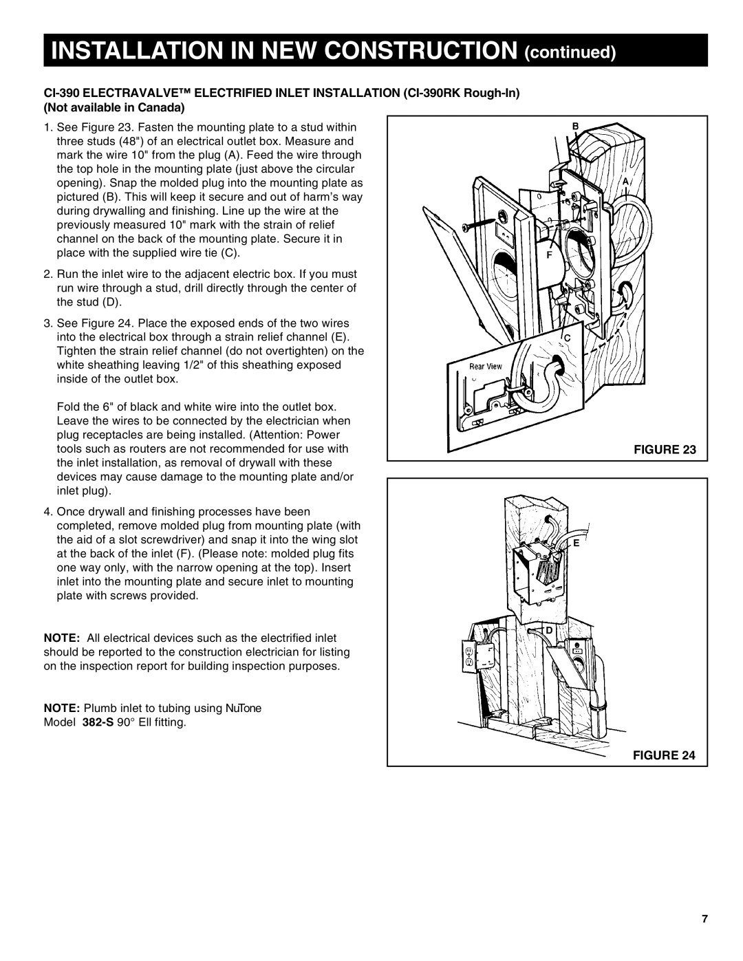
1.See Figure 23. Fasten the mounting plate to a stud within three studs (48") of an electrical outlet box. Measure and mark the wire 10" from the plug (A). Feed the wire through the top hole in the mounting plate (just above the circular opening). Snap the molded plug into the mounting plate as pictured (B). This will keep it secure and out of harm’s way during drywalling and finishing. Line up the wire at the previously measured 10" mark with the strain of relief channel on the back of the mounting plate. Secure it in place with the supplied wire tie (C).
2.Run the inlet wire to the adjacent electric box. If you must run wire through a stud, drill directly through the center of the stud (D).
3.See Figure 24. Place the exposed ends of the two wires into the electrical box through a strain relief channel (E). Tighten the strain relief channel (do not overtighten) on the white sheathing leaving 1/2" of this sheathing exposed inside of the outlet box.
Fold the 6" of black and white wire into the outlet box. Leave the wires to be connected by the electrician when plug receptacles are being installed. (Attention: Power tools such as routers are not recommended for use with the inlet installation, as removal of drywall with these devices may cause damage to the mounting plate and/or inlet plug).
4.Once drywall and finishing processes have been completed, remove molded plug from mounting plate (with the aid of a slot screwdriver) and snap it into the wing slot at the back of the inlet (F). (Please note: molded plug fits one way only, with the narrow opening at the top). Insert inlet into the mounting plate and secure inlet to mounting plate with screws provided.
NOTE: All electrical devices such as the electrified inlet should be reported to the construction electrician for listing on the inspection report for building inspection purposes.
NOTE: Plumb inlet to tubing using NuTone
Model
FIGURE 23
E
D
FIGURE 24
7
